An electronically controlled hydraulic power-assisted brake master cylinder

An electronically controlled hydraulic and brake master cylinder technology, applied in the direction of hydraulic brake transmission, brake, brake transmission, etc., can solve the problems of inaccurate pressure adjustment, large vibration and noise, complex structure, etc., and improve system safety The effects of stability, elimination of noise sources, and low probability of failure

Active Publication Date: 2018-12-21
JILIN UNIV
View PDF7 Cites 0 Cited by
  • Summary
  • Abstract
  • Description
  • Claims
  • Application Information

AI Technical Summary

Problems solved by technology

[0007] The present invention solves the problem that the existing brake system mostly relies on the vacuum degree of the engine or the motor as an energy source, which causes the brake system to fail to realize braking energy recovery, complex structure, large vibration and noise, insufficient rapid active pressure build-up, and insufficient precision of pressure adjustment. , The driver’s pedal force cannot be well utilized, and an electronically controlled hydraulic power-assisted brake master cylinder is proposed. This new master cylinder uses electromagnetic force as an energy source to perform brake boost through a new three-chamber brake master cylinder. , so that the braking system where it is located has the functions of rapid active pressure build-up, precise pressure adjustment, low vibration and noise, failure protection, and full use of the driver's pedal force. Its structure is simple and highly integrated, and it can provide the driver with an ideal pedal. Feel

Method used


Image

  • An electronically controlled hydraulic power-assisted brake master cylinder
  • An electronically controlled hydraulic power-assisted brake master cylinder
  • An electronically controlled hydraulic power-assisted brake master cylinder

Examples


Embodiment Construction

[0048] The present invention is described in detail below in conjunction with accompanying drawing:

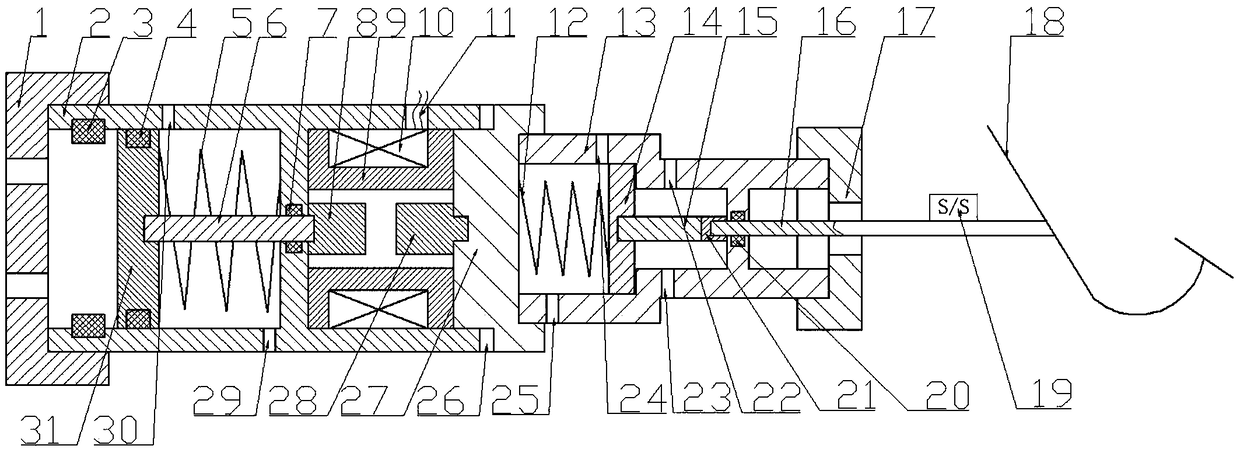
[0049] refer to figure 1 , an electronically controlled hydraulic power-assisted brake master cylinder according to the present invention is composed of an electromagnetic booster mechanism and a three-chamber master cylinder mechanism.

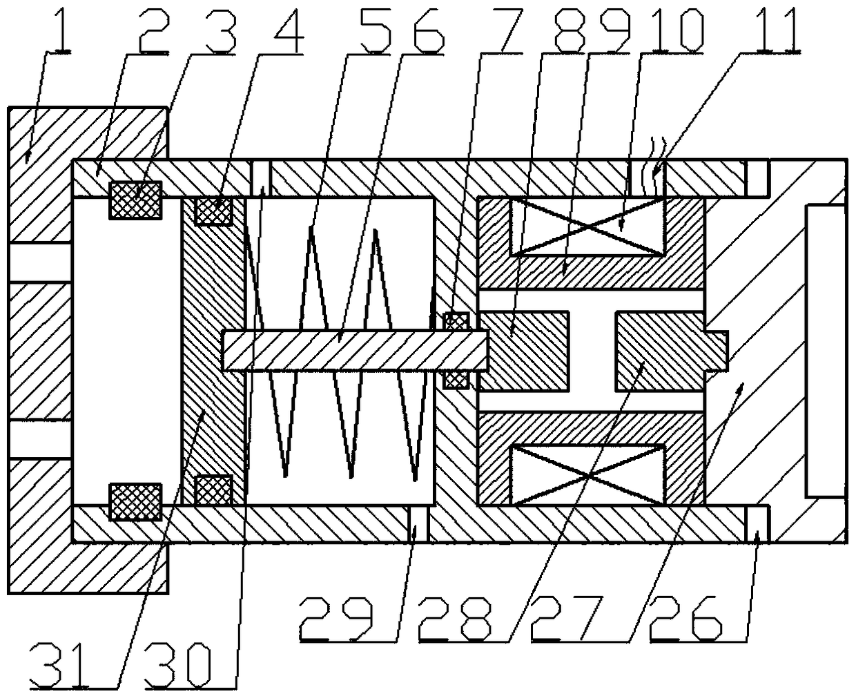
[0050] refer to figure 2 , the electromagnetic boosting mechanism is composed of a hydraulic part and an electromagnetic part.

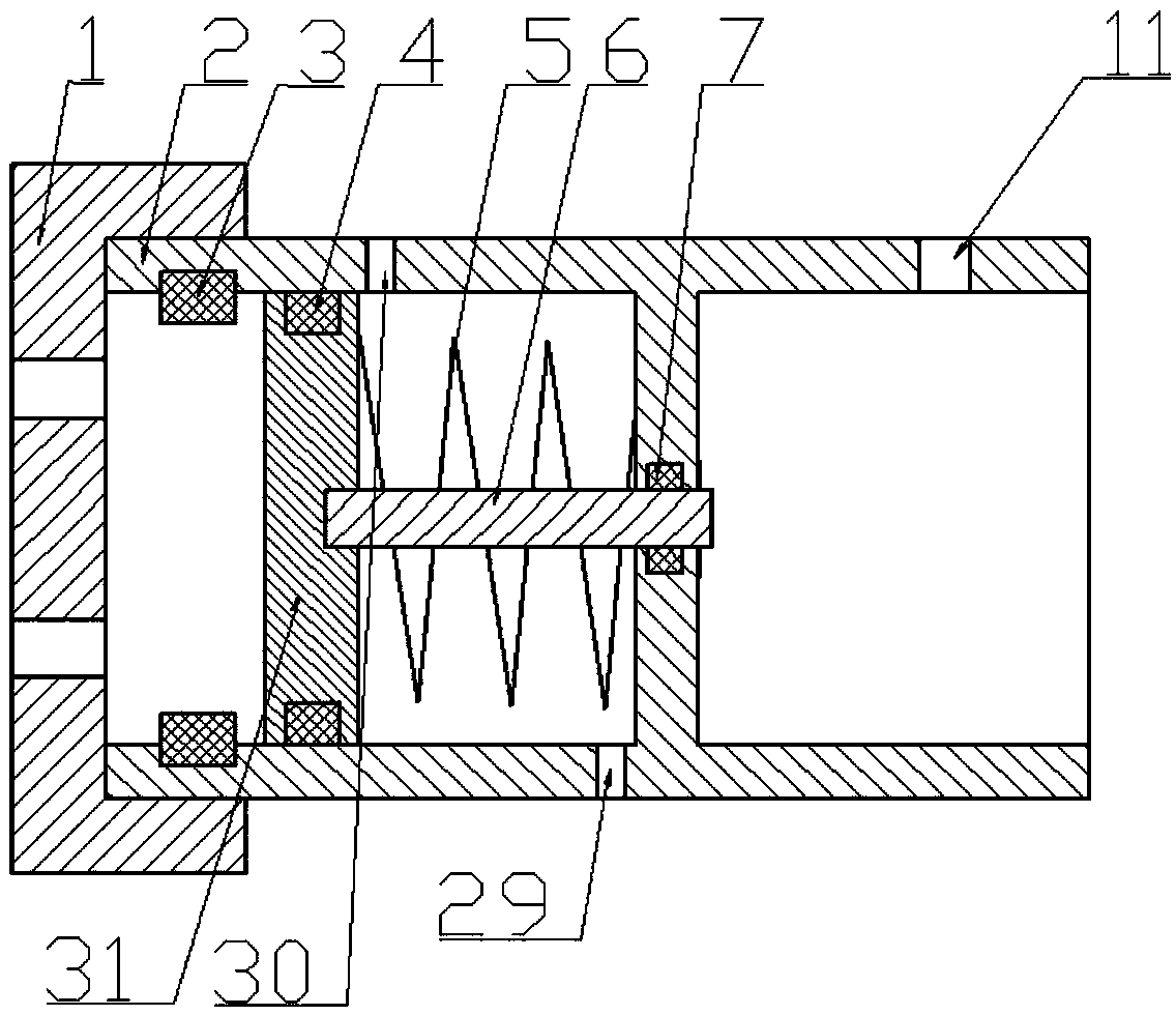
[0051] The structure of the hydraulic part of the electromagnetic booster mechanism is:

[0052] refer to image 3 , the hydraulic part of the electromagnetic boosting mechanism is composed of a booster hydraulic cylinder end cover 1, a booster hydraulic cylinder body 2, a rubber stopper 3, a piston seal ring 4, a booster hydraulic cylinder return spring 5, a booster hydraulic cylinder piston rod 6, Piston rod sealing ring 7, booster hydraulic cylinder piston 31 are formed. Its main function is to generate the...


PUM


Abstract

The invention aims to the solve the problems that the power assisting of an existing brake system usually depends on engine vacuum degree or a motor serving as the energy source, and the brake system cannot recycle brake energy and is complex in structure, large in vibration noise, slow in active pressure building, inaccurate in pressure regulation and incapable of well utilizing driver pedal force and provides an electronically controlled hydraulic power assisted brake master cylinder. The novel electronically controlled hydraulic power assisted brake master cylinder comprises an electromagnetic pressurizing mechanism and a three-cavity master cylinder mechanism. The electronically controlled hydraulic power assisted brake master cylinder has the advantages that the electromagnetic pressurizing mechanism is used as the energy source to perform brake power assisting through the novel three-cavity master cylinder mechanism, so that a brake system with the master cylinder is fast in active pressure building, accurate in pressure regulation, low in vibration noise, capable of achieving failure protection and capable of sufficiently utilizing the driver pedal force; the master cylinder is simple in structure, high in integration level and capable of providing an ideal pedal feeling for a driver.

Description

technical field [0001] The invention belongs to the technical field of brake-by-wire for automobiles, and relates to an electronically controlled hydraulic booster brake master cylinder. Move the master cylinder. Background technique [0002] Summarizing the patents of various brake manufacturers and scholars at home and abroad, it can be found that the innovation of the braking system mainly lies in the innovation of the energy source of the system. Since the entire braking system has no external energy support, it is difficult to meet the braking force required by the braking system only by the braking force of the driver pedaling, so it is necessary to provide a braking energy source for the braking system. The most common Add a vacuum booster to the brake master cylinder, and use the vacuum of the engine to boost the braking system. Due to its simple structure and stable performance, it has dominated the braking system industry for many years. With the development of n...

Claims


Application Information

Patent Timeline
Patent Type & Authority Patents(China)
IPC IPC(8): B60T13/74B60T11/16
CPCB60T11/16B60T13/745
Inventor 李静丁明慧雍文亮韩紫云
Owner JILIN UNIV
Why Eureka
Try Eureka