Non-contact type on-line wheel-set profile detection method based on laser displacement sensor

A technology of laser displacement and detection method, which is applied in the direction of rim measurement/measurement, instruments, measurement devices, etc., can solve the problems of low detection accuracy, high cost, complex structure, etc., and achieves improved detection accuracy, low cost and simple detection principle Effect

Inactive Publication Date: 2017-09-08
NANJING UNIV OF SCI & TECH
View PDF6 Cites 3 Cited by
  • Summary
  • Abstract
  • Description
  • Claims
  • Application Information

AI Technical Summary

Problems solved by technology

The United States, Switzerland, Japan, Russia and other countries have mature technologies in the development of wheel set size automatic detection systems, but their high cost and special requirements for tracks are not suitable for wide application in China
The LY series wheel set fault dynamic detection system produced by Chengdu Leading Technology Co., Ltd. in China adopts light-section image measurement technology and can automatically detect the outer dimensions of the wheels. However, the system has complex structure, high cost, poor anti-interference ability, and low detection accuracy.

Method used


Image

  • Non-contact type on-line wheel-set profile detection method based on laser displacement sensor
  • Non-contact type on-line wheel-set profile detection method based on laser displacement sensor
  • Non-contact type on-line wheel-set profile detection method based on laser displacement sensor

Examples


Embodiment 1

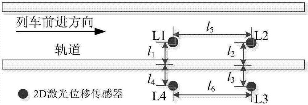
[0049] A first laser displacement sensor L1 and a second laser displacement sensor L2 are sequentially installed along the inner side of the track along the train's forward direction, and a third laser displacement sensor L3 and a fourth laser displacement sensor L4 are sequentially installed on the outer side of the track. The first laser displacement sensor L1 and the fourth laser displacement sensor L4 are arranged symmetrically about the track, and the second laser displacement sensor L2 and the third laser displacement sensor L3 are arranged symmetrically about the track. The vertical installation distance of the first laser displacement sensor L1, the second laser displacement sensor L2, the third laser displacement sensor L3, and the fourth laser displacement sensor L4 from the track l 1 , L 2 , L 3 , L 4 Both are 350mm, the first laser displacement sensor L1 and the second laser displacement sensor L2 horizontal installation distance l 5 Horizontal installation distance f...


PUM


Abstract

The invention discloses a non-contact type on-line wheel-set profile detection method based on laser displacement sensors. The method comprises the following steps: sequentially setting a first laser displacement sensor and a second laser displacement sensor along the inner side of a track in a train advancing direction, and sequentially setting a fourth laser displacement sensor and a third laser displacement sensor on the outer symmetric side of the track, wherein laser sources of the first laser displacement sensor and the second laser displacement sensor are both on a same plane with the upper surface of the track; performing coordinate transformation on data points output from the laser displacement sensors, and extracting end surfaces and key feature points; measuring the distance between the laser displacement sensors and a tire tread when the circle center of a wheel is on central lines of the first laser displacement sensor and the second laser displacement sensor, and calculating the diameter of the wheel according to geometric relationships; and acquiring outlines of two tire treads through data fusion, and further acquiring a mean value of two groups of wheel flange parameters. The method has the advantages of being simple in structure, high in precision and high in stability.

Description

Technical field [0001] The invention belongs to the technical field of railway wheel detection, and particularly relates to a non-contact wheelset size online detection method based on a laser displacement sensor. Background technique [0002] The wheels of urban rail transit vehicles are the coupling parts of the locomotive and the track, which carry the weight of the entire locomotive and ensure the locomotive to run on the track. The wheels constantly rub against the track during operation, causing wear of the wheel treads, and changing the dimensional parameters of the wheel diameter, rim thickness, and rim height, which affect the safe operation of trains and the safety of passengers' lives and property. Therefore, it is of great significance to track and monitor changes in the shape of the wheel tread. [0003] Wheelset size detection system is the focus of rail transit safety operation research, and there are great breakthroughs in research at home and abroad. The United S...

Claims


Application Information

Patent Timeline
IPC IPC(8): B61K9/12G01B11/00
CPCB61K9/12G01B11/00
Inventor 杨志孙飞徐坤朱慕涵邢宗义
Owner NANJING UNIV OF SCI & TECH
Why Eureka
Try Eureka