
A sma-driven helical thermally variable stiffness active control mechanism

An active control and variable stiffness technology, which is applied in the aerospace field, can solve the problems of weak stiffness change control effect, small control force, and large limitation, and achieve a significant stiffness change control effect and the effect of ensuring stiffness requirements

Active Publication Date: 2019-04-12
HARBIN INST OF TECH AT WEIHAI
View PDF8 Cites 0 Cited by
  • Summary
  • Abstract
  • Description
  • Claims
  • Application Information

AI Technical Summary

Problems solved by technology

[0004] In order to solve the problem that the active control mechanism of the thermally variable stiffness of the existing outer thin shell of the aircraft has a small control force during the working process, the control effect on the stiffness change of the material with a relatively high stiffness is relatively weak, and the practical application is relatively limited. Therefore, a SMA-driven helical thermally variable stiffness active control mechanism is proposed

Method used


Image

  • A sma-driven helical thermally variable stiffness active control mechanism
  • A sma-driven helical thermally variable stiffness active control mechanism
  • A sma-driven helical thermally variable stiffness active control mechanism

Examples


specific Embodiment approach 1

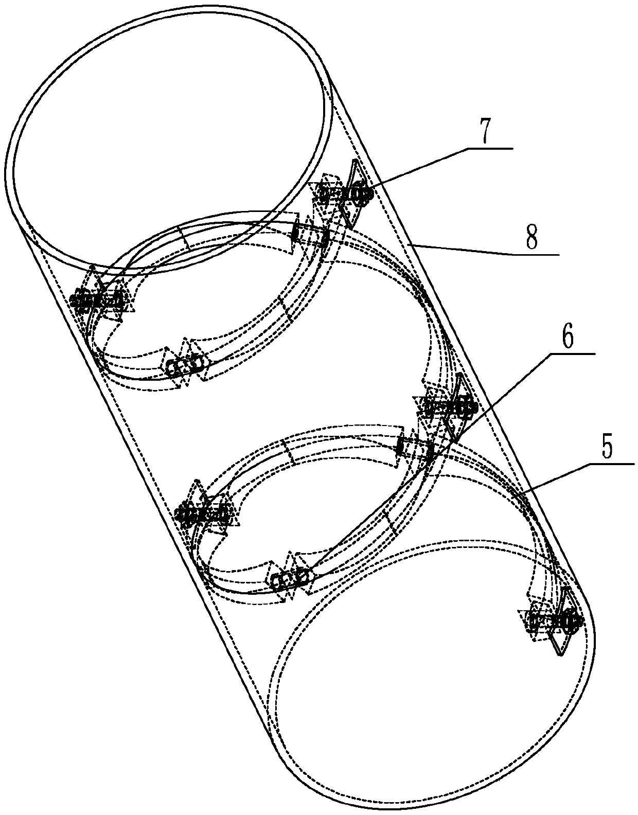
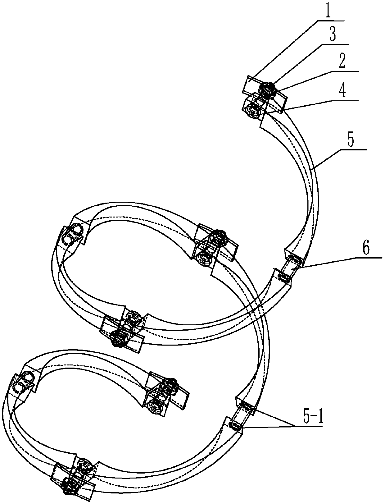
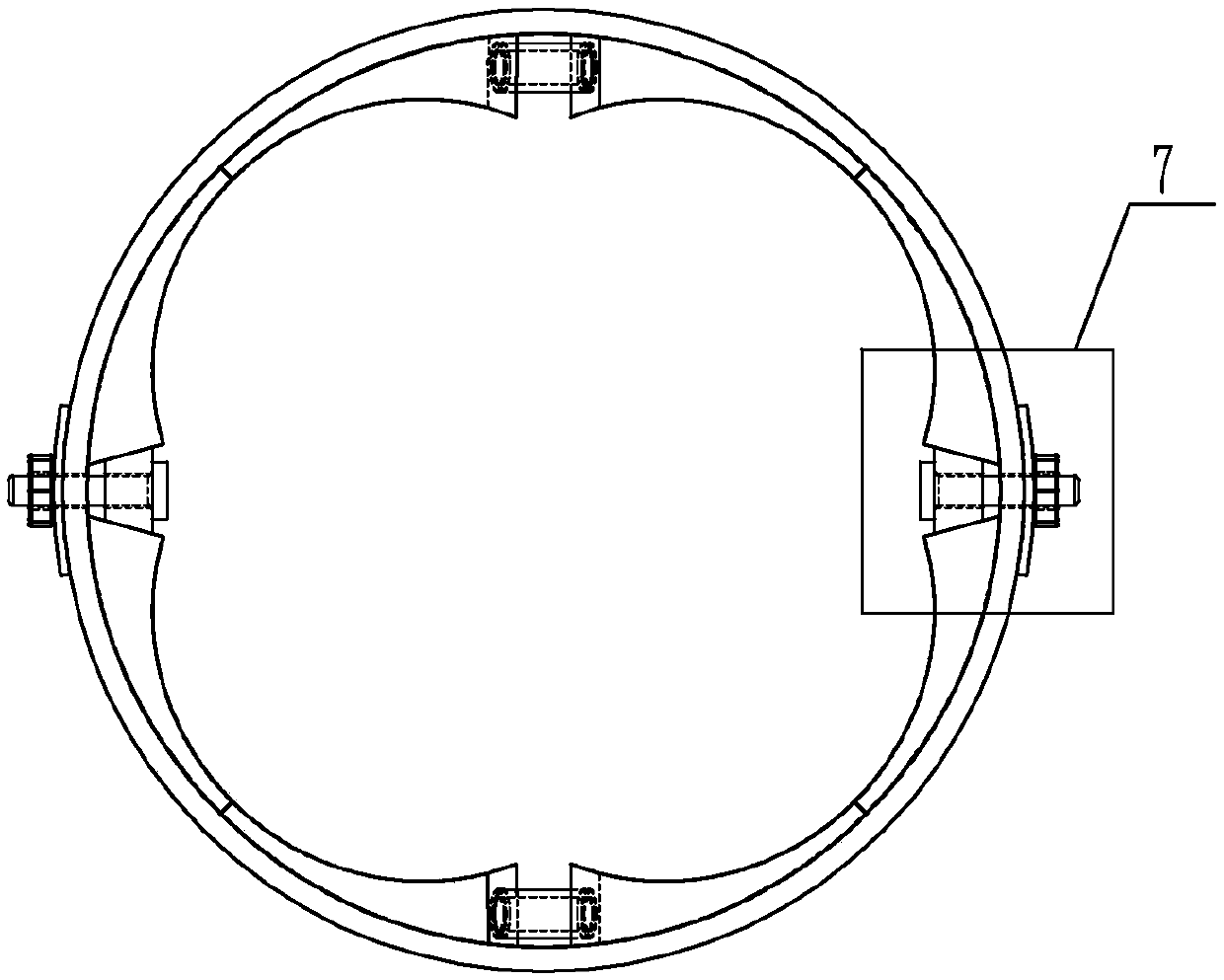
[0018] Specific implementation mode one: combine Figure 1 to Figure 5 To illustrate this embodiment, an SMA-driven helical thermally variable stiffness active control mechanism described in this embodiment includes a plurality of quarter helical expansion rings 5, a plurality of SMA-driven circular tubes 6 and a plurality of pretensioning mechanisms 7, A plurality of quarter helical expansion rings 5 ​​are helically arranged on the inner wall of the cylindrical thin shell 8, the beginning of the first quarter helical expansion ring 5 and the end of the last quarter helical expansion ring 5 pass through The pre-tensioning mechanism 7 is fixedly connected with the thin cylindrical shell 8, and two adjacent quarter spiral expansion rings 5 ​​are connected by SMA driving circular tubes 6 or pre-tensioning mechanisms 7, multiple SMA driving circular tubes 6 and multiple pre-tensioning mechanisms 7 alternate settings.

[0019] This embodiment relates to a thermally variable stiffn...

specific Embodiment approach 2

[0024] Specific implementation mode two: combination Figure 1 to Figure 3 To describe this embodiment, the outer surface of the SMA drive tube 6 in this embodiment is provided with a polyimide heating film. Other compositions and connection methods are the same as those in Embodiment 1.

[0025] In this embodiment, the outer surface of the SMA driving tube 6 is wrapped with polyimide heating film, so that it can be evenly heated during the working process. When working, provide a suitable voltage for the heating film wrapped on the outer surface of the SMA driving round tube 6 .

specific Embodiment approach 3

[0026] Specific implementation mode three: combination Figure 1 to Figure 3 The present embodiment is described. The two end faces of the SMA driving circular pipe 6 in this embodiment are respectively affixed to the end faces of the quarter helical expansion ring 5 . Other compositions and connection modes are the same as those in Embodiment 1 or 2.

[0027] Such a design makes the SMA driving circular tube 6 directly act on the end surface of the quarter helical expansion ring 5 from the end when the SMA driving circular tube 6 is heated.


PUM


Abstract

The invention relates to an SMA-driven spiral heat variable stiffness active control mechanism, which relates to the field of aerospace technology. The present invention aims to solve the problem that the active control mechanism of the thermally variable stiffness of the outer thin shell of the aircraft produces less control force during the working process, and the control effect on the stiffness change of the material with higher stiffness is relatively weak, which is limited in practical application. Big question. The present invention includes multiple quarter-helical expansion rings, multiple SMA driving circular tubes and multiple pre-tightening mechanisms, and multiple quarter-helical expansion rings are spirally arranged on the inner wall of the cylindrical thin shell. The first The beginning of the quarter helical expansion ring and the end of the last quarter helical expansion ring are affixed to the thin cylindrical shell through a pre-tensioning mechanism, and the adjacent two quarter helical expansion rings drive a circular tube or a preloaded tube through SMA. The tightening mechanism is connected, and multiple SMA driving round tubes and multiple pre-tensioning mechanisms are alternately arranged. The invention is used for the thermal variable stiffness control of the outer thin shell of the aircraft.

Description

technical field [0001] The invention relates to the field of aerospace technology, in particular to an SMA-driven spiral thermal stiffness active control mechanism. Background technique [0002] The aircraft will generate a lot of heat during flight, which will affect the steam stiffness of the aircraft. Most of the traditional control methods are to laminate heat-insulating materials and heat-resistant materials on the outer surface of the aircraft to reduce the influence of thermal gradients during flight, or use the Ribs and ribs are arranged on the inner and outer surfaces of the outer shell to enhance the overall rigidity of the outer shell structure of the aircraft. Such control methods are all passive controls, and cannot be adjusted according to changes in the external working environment of the aircraft to optimize the structural stiffness of the aircraft. With the continuous deepening of research on smart materials, piezoelectric materials have been used as sensor...

Claims


Application Information

Patent Timeline
Patent Type & Authority Patents(China)
IPC IPC(8): B64G1/58B64D45/00
CPCB64D45/00B64G1/58
Inventor 王雷岳洪浩武练梅汪豪蒂
Owner HARBIN INST OF TECH AT WEIHAI
Learn More