Swing power tool

A technology of oscillating power tools and reciprocating oscillation, applied in the field of hand-held oscillating power tools, can solve the problems of enlarged machine size and inconvenient operation.

Active Publication Date: 2013-09-18
POSITEC POWER TOOLS (SUZHOU) CO LTD
View PDF7 Cites 13 Cited by
  • Summary
  • Abstract
  • Description
  • Claims
  • Application Information

AI Technical Summary

Problems solved by technology

[0006] However, in the above-mentioned structure, since it is necessary to set the toggle member and make the eccentric member and the toggle member move axially together, it is necessary to reserve enough space, so that the size of the entire machine becomes larger and the operation is inconvenient

Method used


Image

  • Swing power tool
  • Swing power tool
  • Swing power tool

Examples


specific Embodiment approach 1

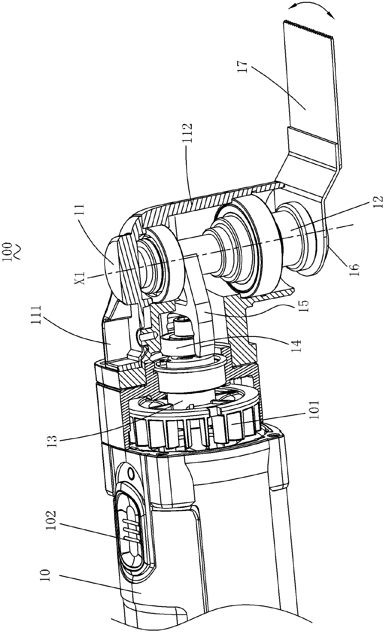
[0063] see image 3 , a swing power tool, specifically a multifunctional machine 100, which includes a longitudinally extending casing 10 connected to the front end of the casing 10 (with figure 1 The middle right side is defined as the head shell 11 of the front end) and the output shaft 12 extending from the head shell 11 . Wherein, a motor 101 is arranged inside the casing 10 , and a switch 102 is also arranged on the casing 10 to control the turning on or off of the motor 101 . A drive shaft 13 extends laterally from the motor 101 , and the drive shaft 13 rotates under the drive of the motor 101 . The head shell 11 is connected with the casing 10 and along the figure 1 The horizontal portion 111 is arranged in the horizontal direction and the vertical portion 112 extends substantially vertically downward from the end of the horizontal portion 111 . The output shaft 12 is arranged in the vertical direction, one end of which is installed in the head shell 11, and the othe...

specific Embodiment approach 2

[0082] In the above-mentioned first embodiment, the first stop surface on the first limiter of the transmission member and the second stop surface of the second limiter on the balance weight are both set to form a clip with respect to the axis of the eccentric shaft. horn. That is to say, both the first stopper of the transmission member and the second stopper of the second limiter have a certain taper, and both the first stopper surface and the second stopper surface form a certain slope along the axis of the eccentric shaft. Apparently, the first stop surface and the second stop surface can also be set as planes parallel to the axis of the eccentric shaft, which can also realize the adjustment of the eccentricity of the transmission member relative to the drive shaft. Combine below Figure 13 to Figure 15 , briefly describe the second embodiment of the present invention.

[0083] In this embodiment, the difference from the oscillating power tool 100 in the first embodiment...


PUM


Abstract

The invention discloses a swing angle-adjustable swing power tool, which comprises a shell, a motor, a drive shaft, an eccentric shaft, an output shaft and a swing mechanism, wherein the drive shaft does a rotation motion under the drive of the motor; the eccentric shaft is connected with the tail end of the drive shaft; the axis of the eccentric shaft is eccentrically arranged relative to the axis of the drive shaft; the output shaft can do a rotation reciprocating swing motion around the axis of the output shaft, and is used for installing and driving a working head to work; and the swing mechanism is arranged between the drive shaft and the output shaft. The swing mechanism comprises a transmission part and a shifting fork, wherein the transmission part is arranged on the eccentric shaft, and the shifting fork is arranged on the output shaft and is matched with the transmission part. The center line of the transmission part is eccentrically arranged relative to the axis of the eccentric shaft, and the transmission part can rotationally move between at least two fitting locations around the eccentric shaft, so that the center line of the transmission part has at least two different eccentric distances relative to the axis of the drive shaft. The swing angle-adjustable swing power tool is simple in structure and small in size.

Description

technical field [0001] The invention relates to a power tool, in particular to a hand-held oscillating power tool. Background technique [0002] The multi-function machine is a common hand-held oscillating power tool in the industry. Its working principle is that the output shaft performs oscillating motion around its own axis. Therefore, when the user installs different working heads on the free end of the output shaft, such as straight saw blades, circular saw blades, triangular abrasive discs, and shovel scrapers, a variety of different operating functions can be realized, such as sawing, cutting, etc. , grinding, scraping, etc., to suit different work needs. [0003] specific reference figure 1 and figure 2 , an existing oscillating power tool 100' includes a casing 1', an output shaft 2' extending from the casing 1', a motor 11' set in the casing 1' and a motor driven by the motor 11'. Main axis 4'. One end of the main shaft 4' is connected with a connecting shaft...

Claims


Application Information

Patent Timeline
Patent Type & Authority Applications(China)
IPC IPC(8): B25F5/00
Inventor 张士松孙益民钟红风徐静涛霍立祥
Owner POSITEC POWER TOOLS (SUZHOU) CO LTD
Why Eureka
Try Eureka