
Turbine movable blade pressure surface and top compound angle film hole layout structure

A technology of layout structure and compound angle, applied in the directions of engine components, machines/engines, blade support components, etc., can solve the problems of the influence of the mainstream aerodynamic performance on the blade surface, the complex air film hole structure, and the increase of aerodynamic losses, so as to increase the air flow rate. Membrane coverage area, overcoming adverse effects, reducing the effect of aerodynamic losses

Active Publication Date: 2017-09-08
INST OF ENGINEERING THERMOPHYSICS - CHINESE ACAD OF SCI
View PDF5 Cites 4 Cited by
  • Summary
  • Abstract
  • Description
  • Claims
  • Application Information

AI Technical Summary

Problems solved by technology

However, the structure of air film holes such as special-shaped holes is relatively complicated, and the processing is difficult and costly.
At the same time, it has a certain impact on the mainstream aerodynamic performance of the blade surface and increases the aerodynamic loss

Method used


Image

  • Turbine movable blade pressure surface and top compound angle film hole layout structure
  • Turbine movable blade pressure surface and top compound angle film hole layout structure
  • Turbine movable blade pressure surface and top compound angle film hole layout structure

Examples


Embodiment Construction

[0049] In order to make the object, technical solution and advantages of the present invention clearer, further detailed description will be given below with reference to the accompanying drawings.

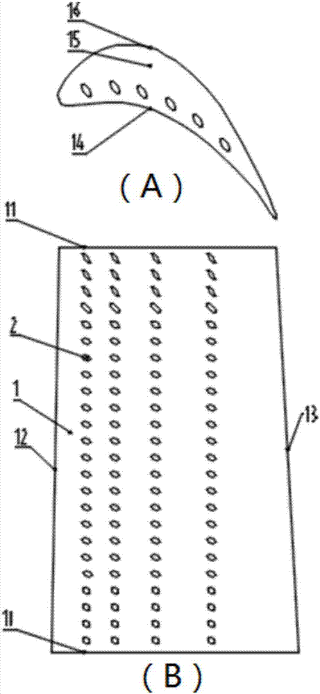
[0050] Such as figure 1Shown, the present invention is applicable to the compound angle film hole layout structure of aero-engine turbine blade pressure surface and top, turbine blade 1 comprises blade root 10, blade tip 11, leading edge 12 and trailing edge 13, turbine blade The pressure surface 14 of 1 is provided with 4 rows of compound corneum holes 2 arranged in parallel along the entire spanwise area from the blade root to the blade tip, and the top 15 of the turbine rotor blade 1 is provided with a row of compound corneum holes 2. The membrane hole 2 is in communication with the cooling air flow chamber inside the turbine blade 1 . The first row of holes is located at 0.12 times the chord length, the second row of holes is located at 0.25 times the chord length, the third ...


PUM


Abstract

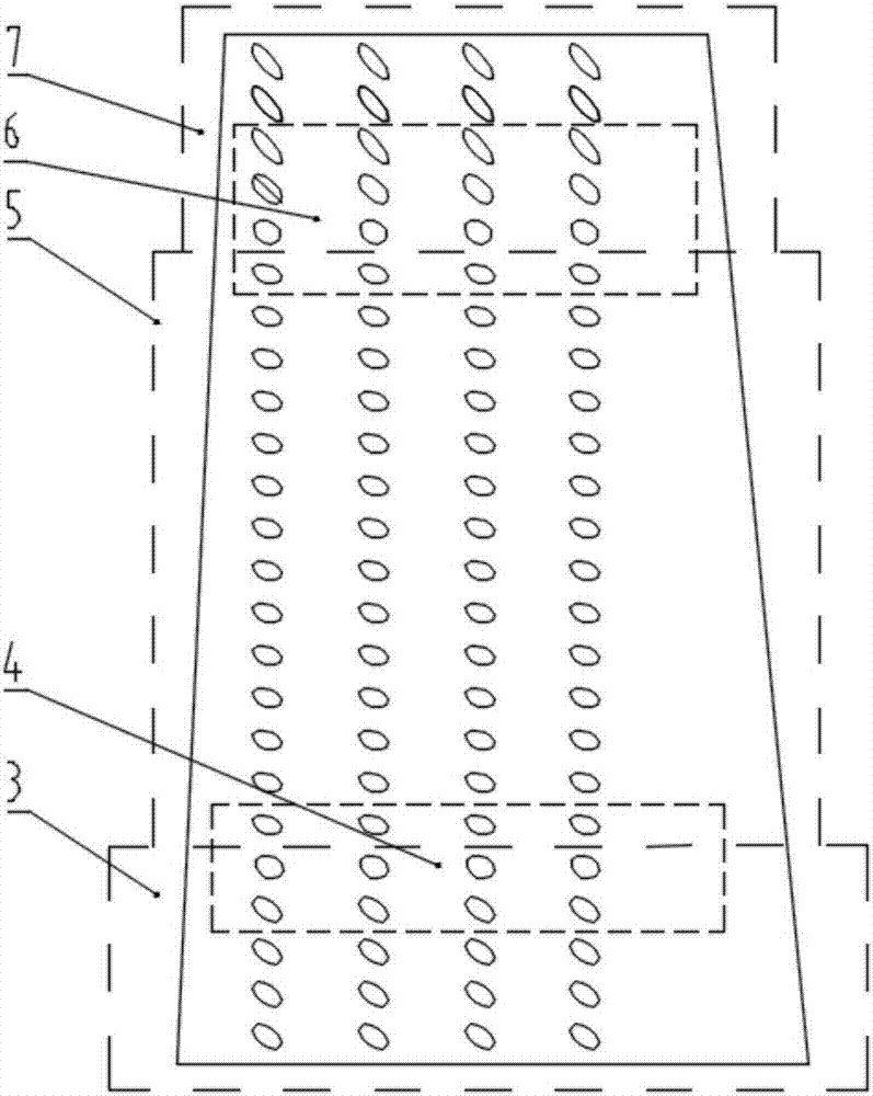
The invention discloses a turbine movable blade pressure surface and a compound angle film hole layout structure at the top, is suitable for an aircraft engine or a ground gas turbine, and relates to the field of aircraft engine turbine blade cooling. Aiming at deflection of film outlet currents at the top of the blade pressure surface in a rotating state from blade root to blade tip to different extents, the detailed subarea compound angle design is performed; the turbine movable blade pressure surface is divided into five different blade areas of a blade root area, a blade root-blade middle transition area, a blade middle area, a blade middle-blade tip transition area and a blade tip area; and in consideration of the blade top, each blade area is provided with different compound angle film holes, so that the technical problem of no facilitation of wall attachment of films due to deflection of the film outlet currents of the pressure surface to the blade tip under the influence of the Coriolis Force pointed to the blade tip, the centrifugal floating force pointed to the blade tip and the secondary channel current and caused by leakage of the currents from top gaps is solved, the film covering is more uniform, and the cooling efficiency is improved.

Description

technical field [0001] The invention relates to the technical field of aeroengine / gas turbine turbine blade cooling, in particular to an optimized layout structure of air film holes on the pressure surface and top of a turbine rotor blade, a hot end part of an aeroengine / gas turbine. Different from the air film hole design that is only aimed at the flow stability area in the middle of the blade, this structure is based on the flow characteristics of different regions, and the pressure surface of the turbine rotor blade is comprehensively divided into sub-areas from the blade tip to the top. Designed to meet the cooling requirements of modern high-performance aero-engines / gas turbines for hot-end components. Background technique [0002] For modern high-performance aeroengines, in order to pursue higher thrust-to-weight ratio and thermal efficiency, it is necessary to continuously increase the turbine inlet temperature. Film cooling technology has become particularly importa...

Claims


Application Information

Patent Timeline
Patent Type & Authority Applications(China)
IPC IPC(8): F01D5/18
CPCF01D5/186
Inventor 李国庆徐纲朱俊强
Owner INST OF ENGINEERING THERMOPHYSICS - CHINESE ACAD OF SCI
Learn More