Phase modifier stationing method for preventing multi-DC chain commutation failure

A technology of phase commutation failure and camera adjustment, applied in AC network circuits, power transmission AC networks, reactive power adjustment/elimination/compensation, etc., can solve problems such as failure to consider dynamic interaction effects, inconsistencies with actual conditions, and dangers, etc. Achieve the effect of solving the problem of chain commutation failure, suppressing chain commutation failure, and reducing configuration capacity

Active Publication Date: 2017-09-08
NARI TECH CO LTD +3
View PDF5 Cites 25 Cited by
  • Summary
  • Abstract
  • Description
  • Claims
  • Application Information

AI Technical Summary

Problems solved by technology

In some cases, it is difficult to truly reflect the dynamic interaction between the disturbed commutation bus voltage and DC current, and it is also difficult to adapt to the system operation by only relying on the traditional method of judging the commutation failure based on the drop of the commutation bus voltage amplitude. Changes in the dynamic interaction behavior of AC and DC, which may cause the results obtained by using these indicators to be inconsistent with the actual situation
[0006] Therefore, because the traditional dynamic reactive device layout method does not consider the dynamic interaction between the commutation bus voltage and DC current in the actual operation of the AC-DC grid, the results obtained by using these layout methods are inconsistent with the actual situation and may even be Therefore, there is a danger of deteriorating the operational performance of the AC and DC grid, causing serious consequences in terms of grid security or economy

Method used


Image

  • Phase modifier stationing method for preventing multi-DC chain commutation failure
  • Phase modifier stationing method for preventing multi-DC chain commutation failure
  • Phase modifier stationing method for preventing multi-DC chain commutation failure

Examples


Embodiment 1

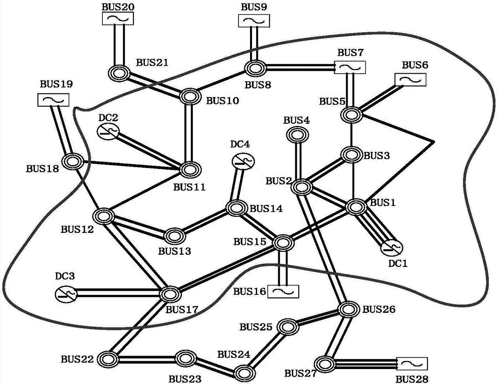
[0038] An embodiment of the present invention, which takes an actual power grid as an example, aims at suppressing cascading commutation failures of AC and DC power grids, mainly including multiple DC simultaneous commutation failures and sequential commutation failures to implement phase adjustment control points. In 2016, the actual power grid had seven direct current circuits, forming a typical multi-infeed direct current transmission system. The rated transmission power of each direct current is shown in Table 1.

[0039] Table 1 DC rated transmission power

[0040]

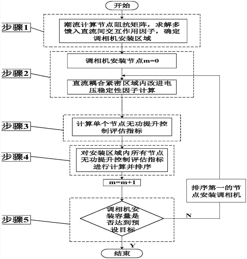
[0041] In this embodiment, the steps of the method for distributing the cameras are as follows: figure 1 shown. figure 1 In step 1, it is described to determine the area where the risk of other DC commutation failures at the same time or successively after the failure of DC commutation is determined, and this area is determined as the installation area of ​​the condenser. Specifically, the multi-circuit D...


PUM


Abstract

The invention discloses a phase modifier stationing method for preventing multi-DC chain commutation failure, and belongs to the technical field of automation of a power system. A region with a relatively high risk that other DCs are simultaneously or sequentially failure in commutation caused by a commutation failure of a certain DC according to a multi-fed interactive factor is judged, the region is used as an installation region of a phase modifier, and the optimal phase modifier installation place is obtained by calculating and sequencing reactive power improvement control estimation indexes of the phase modifier. By the method, the problems that the commutation failure is judged only by voltage drop of a commutation bus and the inconsistency of a result and an actual condition probably caused by a relevant phase modifier configuration index obtained according to the type of the commutation failure cannot be effectively reflected are solved, and the configuration capacity of the phase modifier is reduced to the great extent on the basis of ensuring rapid recovery of the DC with commutation failure.

Description

technical field [0001] The invention belongs to the technical field of electric power system automation, and in particular the invention relates to a method for distributing points of a controller for suppressing the failure of multi-DC chain commutation. Background technique [0002] In a multi-infeed DC system, if the electrical coupling between the DC converter stations is tight and the strength of the connected AC system is insufficient, a short-circuit fault of a DC near-area AC line is likely to cause simultaneous or successive commutation failures of multiple DCs. , which will have a large power impact on the receiving end system. If the DC system fails for a long time and continues to commutate, it may cause the DC system to be blocked, causing the interruption of DC power transmission, easily leading to the transient instability of the AC system, and even causing a series of The cascading failures eventually lead to a major blackout. [0003] At present, the use of...

Claims


Application Information

Patent Timeline
Patent Type & Authority Applications(China)
IPC IPC(8): H02J3/00H02J3/36H02J3/18
CPCH02J3/00H02J3/18H02J3/36H02J2203/20Y02E40/30Y02E60/60
Inventor 方勇杰侯玉强刘亚仁李威王玉刘福锁彭慧敏李丹黄志龙曹路李海峰庄侃沁
Owner NARI TECH CO LTD
Why Eureka
Try Eureka