
Stabilizing fin execution mechanism capable of realizing large fin rotating angle

An actuator and anti-rolling fin technology, which is applied to equipment for reducing the rolling motion of boats, and the field of zero-speed anti-rolling fins, which can solve the problem of not meeting the requirements for anti-rolling of ships, large weight and cabin space, and difficult cabin space layout, etc. problem, to achieve the effect of compact structure, weight reduction, and reduction of cabin space

Active Publication Date: 2017-09-12
SHANGHAI HUNTER MARINE EQUIP CO LTD
View PDF3 Cites 2 Cited by
  • Summary
  • Abstract
  • Description
  • Claims
  • Application Information

AI Technical Summary

Problems solved by technology

Although this design takes into account ordinary fin stabilizers, it only needs to design and maintain a set of equipment, and the cost and volume do not increase much, but it is limited by the maximum fin fins that can be achieved because the actuators use the drive structure of crank connecting rods. The congenital deficiency of the working angle is only ±40°, and the anti-rolling effect at zero speed is limited, which cannot meet the anti-rolling requirements of ships at low or even zero speeds. come difficult

Method used


Image

  • Stabilizing fin execution mechanism capable of realizing large fin rotating angle
  • Stabilizing fin execution mechanism capable of realizing large fin rotating angle
  • Stabilizing fin execution mechanism capable of realizing large fin rotating angle

Examples


Embodiment Construction

[0020] The present invention will be further described below in conjunction with the accompanying drawings and embodiments.

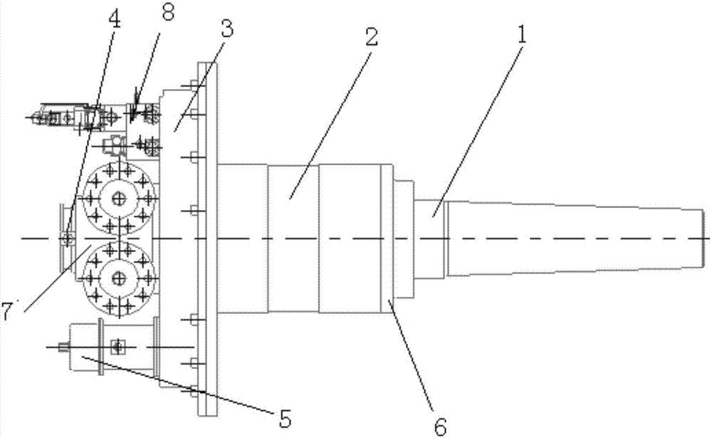
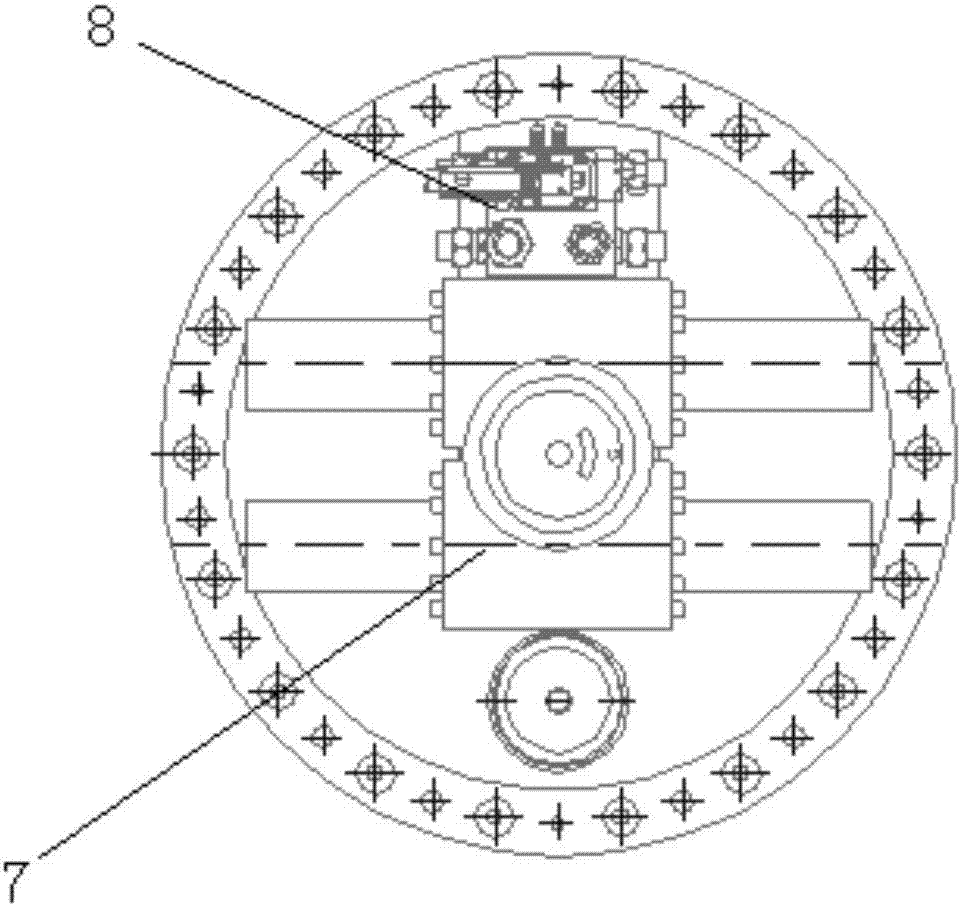
[0021] Such as Figure 1 to Figure 6 As shown, a fin stabilizer actuator that can achieve large fin angle rotation mainly includes a fin shaft group 1, a support seat, a fin angle transmitter 4, a locking mechanism 5, a seawater sealing device 6, a rack and pinion cylinder 7 and Control valve group 8 and so on.

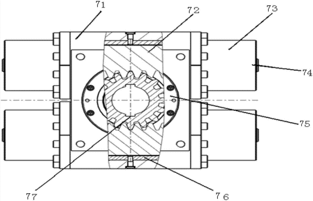
[0022] The rack and pinion cylinder 7 is installed on the front end of the support seat, and is connected with the fin shaft group 1 installed on the rear end of the support seat, and is used to drive the fin shaft group 1 to rotate. The rack and pinion cylinder 7 is composed of a casing 71, a cylindrical rack 72, a cylinder cylinder 73, self-lubricating complete set 76 and gear shaft 77; two cylindrical racks 72 and a gear shaft 77 are integrated in the box body 71, the gear shaft 77 is connected with the fin shaft group 1, and the two cylind...


PUM


Abstract

The invention relates to a stabilizing fin execution mechanism capable of realizing a large fin rotating angle. A gear-rack cylinder is installed at the front end of a supporting seat and connected with a fin shaft group installed at the rear end of the supporting seat, two cylindrical racks and a gear shaft of the gear-rack cylinder are integrated inside a box body, the hollow gear shaft is connected with the fin shaft group by virtue of a key, the two cylindrical racks are arranged at the upper end and the lower end of the gear shaft and engaged with the gear shaft, two ends of each cylindrical rack are respectively arranged in a cylinder barrel fixed at two sides of the box body and forms a diagonal double-gear cavity, the diagonal double-gear cavity is connected to a driving source hydraulic unit by virtue of an oil pipe, the two cylindrical racks transfer the hydraulic pressure to the gear shaft by virtue of the engagement of the gear, so that the reciprocating rectilinear movement of the cylindrical racks is converted to the swinging of the fin shaft group. The stabilizing fin execution mechanism is simple and compact in structure, the cabin occupation space of the execution mechanism can be obviously reduced, a working angle can reach up to + / -65 degrees, the rotating angle requirement at the zero speed can be satisfied, a good stabilizing effect can be ensured, and the reliability of the system can be greatly improved.

Description

technical field [0001] The invention relates to a device for reducing rolling motion of a ship, in particular to a fin stabilizer at zero speed, and belongs to the technical field of fin stabilizer actuators. Background technique [0002] Existing fin stabilizers can provide a variety of anti-roll configuration schemes for various ships, and the technology is relatively mature to ensure that ships have good anti-roll requirements at medium / high speeds. The demand for anti-rolling at sea speed is becoming increasingly urgent. For this reason, a comprehensive anti-rolling system combining the anti-rolling water tank and the fin stabilizer has been developed in China, that is, the anti-rolling water tank is used for anti-rolling at zero speed, and the anti-rolling water tank is used at medium / high speed. The combination of tank and fin stabilizer requires design, installation and maintenance of two sets of independent equipment, which is not economical, and takes up a lot of sp...

Claims


Application Information

Patent Timeline
Patent Type & Authority Applications(China)
IPC IPC(8): B63B39/06
CPCB63B39/06
Inventor 毛杨军邓启亮彭杉牛远振何彩繁
Owner SHANGHAI HUNTER MARINE EQUIP CO LTD
Learn More