Barrel plating anode electrolytic plate with novel structure

A technology of anode electrolysis and new structure, applied in electrodes and other directions, can solve the problems of low current utilization rate, singleness, and low deposition rate of electroplating coating.

Inactive Publication Date: 2017-09-12
湖北协兴环保科技股份有限公司
View PDF0 Cites 2 Cited by
  • Summary
  • Abstract
  • Description
  • Claims
  • Application Information

AI Technical Summary

Problems solved by technology

[0004] The object of the present invention is to provide a kind of barrel plating anode electrolytic plate of new structure, to solve the existing electrolytic anode plate shape that is used for barrel plating that proposes in the above-mentioned background technology mostly is a single I-shaped structure, the problem of this regular structure The area of ​​the anode plate is small, and the current utilization rate during the electroplating process is low, resulting in a low deposition rate of the electroplating coating, which affects work efficiency.

Method used


Image

  • Barrel plating anode electrolytic plate with novel structure
  • Barrel plating anode electrolytic plate with novel structure

Examples


Embodiment Construction

[0016] Hereinafter, embodiments of the present invention will be described in detail, examples of which are shown in the accompanying drawings and the following description. While the invention will be described in conjunction with exemplary embodiments, it will be understood that the description is not intended to limit the invention to the exemplary embodiments. On the contrary, the invention is to cover not only the exemplary embodiment, but also various alternatives, modifications, equivalents and other embodiments, which may be included within the spirit and scope of the invention as defined by the appended claims Inside.

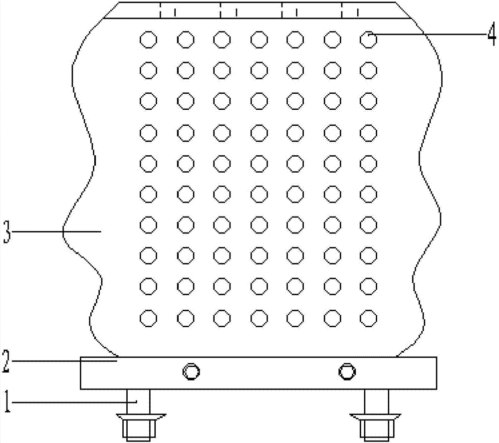
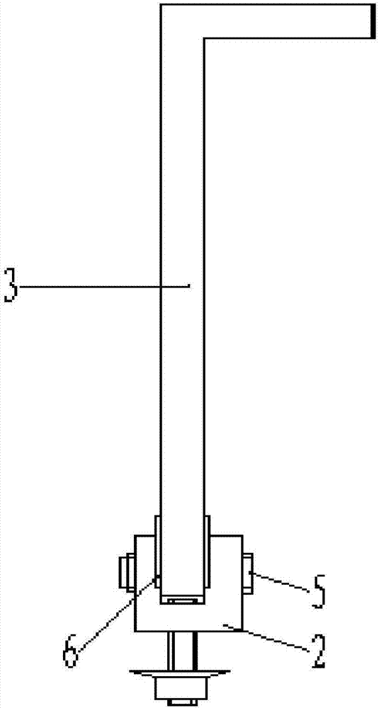
[0017] see figure 1 to attach figure 2 , a barrel-plated anode electrolytic plate with a new structure, including:

[0018] Electrolytic stud 1, alloy hanging plate 2, anode electrolytic plate 3, vent hole 4, fixing bolt 5 and conductive copper strip 6;

[0019] The electrolytic stud 1 is threaded on the bottom side of the alloy hanging plate 2, a...


PUM


Abstract

A barrel-plated anode electrolytic plate with a new structure, including electrolytic studs, alloy hanging plates, anode electrolytic plates, air holes, fixing bolts and conductive copper strips; the electrolytic studs are threaded on the bottom side of the alloy hanging plate, and Both sides of the U-shaped inner side of the alloy hanging plate are inlaid with long strips of conductive copper strips. One end of the anode electrolytic plate is installed on the alloy hanging plate through fixing bolts, and the anode electrolytic plate is covered with a plurality of plates for electroplating solution. Ventilation holes for liquid circulation; the anode electrolytic plate is in contact with the conductive copper strip, so that the current connected to the external anode wire end is quickly transferred to the anode electrolytic plate through the conductive copper strip, and the periphery of the entire anode plate is made into a wave image The structure makes the area of ​​the anode plate larger than the area of ​​the supporting cathode plate, so that the current utilization rate in the electroplating process is improved, resulting in faster precipitation of the electroplating coating, and improving work efficiency. In order to further improve the utilization rate of the anode plate current.

Description

technical field [0001] The invention relates to the technical field of electrolytic barrel plating of industrial products, in particular to a barrel plating anode electrolytic plate with a new structure. Background technique [0002] The inventors found that the existing electrolytic anode plates used for barrel plating mostly have a single I-shaped structure, and the area of ​​the anode plates with this regular structure is small, and the current utilization rate in the electroplating process is low, resulting in the precipitation of the electroplating coating The speed is low, affecting work efficiency. [0003] Therefore, in view of this, the inventor has been adhering to many years of rich experience in design, development and actual production in this related industry, researched and improved the existing structure and defects, and provided a barrel-plating anode electrolytic plate with a new structure, in order to achieve more. more practical purposes. Contents of t...

Claims


Application Information

Patent Timeline
Patent Type & Authority Applications(China)
IPC IPC(8): C25D17/12
CPCC25D17/12
Inventor 张辉华裴虎陈立学袁铭张欢
Owner 湖北协兴环保科技股份有限公司
Why Eureka
Try Eureka