
Light Module

An optical module and optical technology, applied in the field of optical modules, can solve the problems of impracticality, expensive processing and manufacturing failure, and complex automated production line manufacturing, and achieve the effects of simple fixation, simplified assembly, and cost reduction.

Active Publication Date: 2017-09-12
LEDVANCE GMBH
View PDF4 Cites 1 Cited by
  • Summary
  • Abstract
  • Description
  • Claims
  • Application Information

AI Technical Summary

Problems solved by technology

Manufacture in an automated production line is complex or impracticable by individual components
Fixing by individual components, depending on tolerances and manufacturing problems, often leads to very expensive subsequent processing and to possible manufacturing faults

Method used


Image

  • Light Module
  • Light Module
  • Light Module

Examples


Embodiment Construction

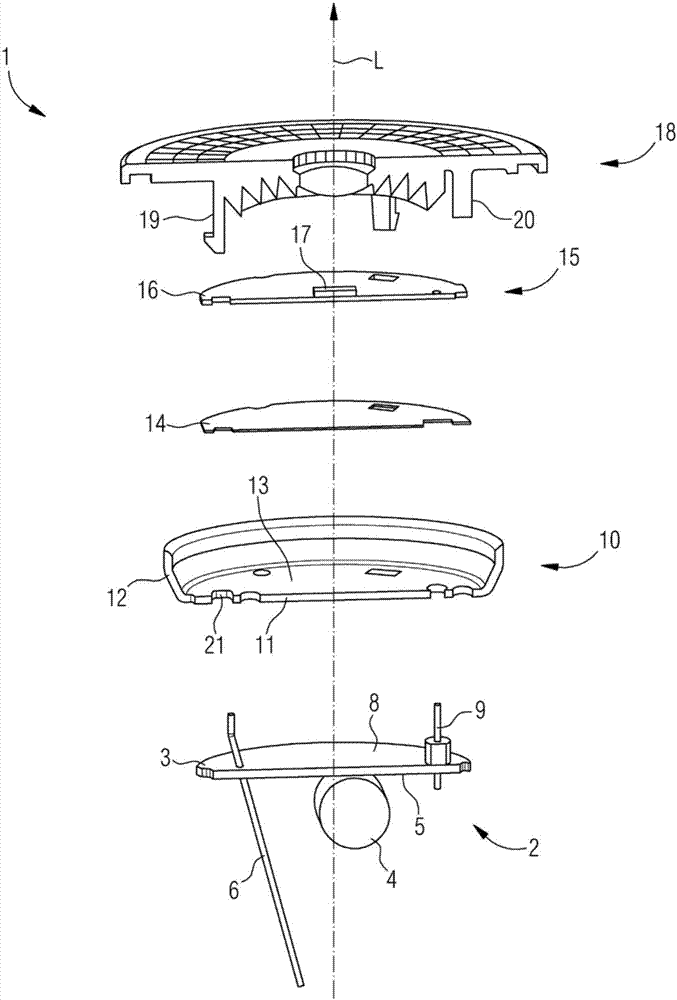
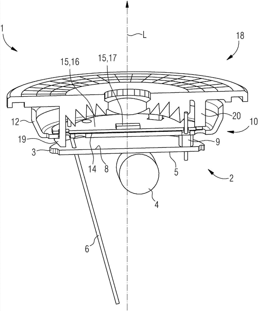
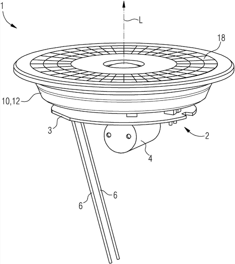
[0044] figure 1 Shown to be assembled into optical module 1 (referring to figure 2 or image 3 ) side view of a single element. These elements comprise a driver 2 with a driver circuit board 3 perpendicular to the longitudinal axis L. Electrical and / or electronic components 4 are arranged on the driver circuit board, ie in particular on the rear side 5 . Conductive contact cables 6 protrude from the back side 5, ie at the contact portion towards the contact pin 7 (see Figure 5 ) direction. The front side 8 of the driver circuit board 3 is equipped with solder pins or feet 9 protruding forward (in the longitudinal direction L).

[0045] The other part is a shell-shaped cooling body 10 having a disc-shaped planar bottom 11 oriented perpendicular to the longitudinal axis L and lateral walls 12 adjoining transversely forward.

[0046] A TIM film 14 is arranged on the front face 13 of the base 11 .

[0047] Arranged in front of the TIM film 14 is a light emitter 15 with a...


PUM


Abstract

A light module (1) serves for inserting into a housing (23) of a semiconductor lamp (24) and comprises: a driver (2), a cooling element (10), a light generator (15), abutting the cooling element, with at least one semiconductor light source (17), which is electrically connected with the driver (2), and an optical refraction element (18) covering the at least one semiconductor light source, wherein the refraction element is fastened on the cooling element and presses the light generator (15) onto the cooling element. A semiconductor lamp (24) comprises a housing open at the front into which the light module is inserted from the front side and on which the light module is fastened. A method serves for producing a semiconductor lamp, wherein at least the driver, the cooling element, the light generator and the refraction element are assembled into an individually manageable light module and the light module is then inserted into a housing. The invention is also applicable to replacement or retrofit lamps, in particular with a pin base, particularly a bipin base, e.g. to retrofit lamps for replacing halogen lamps, for example of the type MR16.

Description

technical field [0001] The invention relates to an optical module for being inserted into a housing of a semiconductor lamp, the optical module has: a driver, a cooling body, a light emitter with at least one semiconductor light source attached to the cooling body, the semiconductor light source and the driver circuit connected, and at least one optical refraction element covering the semiconductor light source. The invention also relates to a semiconductor lamp having a housing which is open on the front side and a light module. Furthermore, the invention relates to a method for manufacturing a semiconductor lamp. The invention can be used in particular for replacement lamps or retrofit lamps, in particular with a tube base, in particular a pin base, for example for retrofit lamps of the type MR16 or PAR16 for replacing halogen lamps. Background technique [0002] LED replacement lamps or retrofit lamps have heretofore been assembled from a plurality of individual compone...

Claims


Application Information

Patent Timeline
IPC IPC(8): F21K9/20F21K9/90F21V17/10F21V17/16F21V19/00F21V23/00F21V29/503F21Y115/10
CPCF21K9/90F21V17/101F21V17/164F21V19/005F21V23/003F21V29/503F21V5/045F21V23/001F21V23/005F21V29/70F21V29/89F21K9/233F21Y2115/10F21V5/10F21K9/20
Inventor 托马斯·克拉夫塔约翰·霍兰马丁·勒夫马赛尔·武克约瑟夫·迈道
Owner LEDVANCE GMBH
Learn More