
Special toughened glass automatic placing frame for high-rise building curtain wall

A technology for tempered glass and high-rise buildings, which is applied in tool storage devices, packaging of fragile items, and manufacturing tools, etc., which can solve problems such as increasing the labor intensity of staff, increasing the difficulty of glass loading and unloading, and reducing work efficiency, so as to reduce work efficiency , increase the labor intensity, the effect of high work efficiency

Inactive Publication Date: 2017-09-15
安徽海之纳科技有限公司
View PDF0 Cites 12 Cited by
  • Summary
  • Abstract
  • Description
  • Claims
  • Application Information

AI Technical Summary

Problems solved by technology

[0003] In order to solve the above problems, the present invention provides a special tempered glass automatic placement rack for high-rise building curtain walls, which can solve the problem of manually selecting the corresponding glass placement rack according to different glass sizes in the placement process of the existing glass after processing. The frame cannot be automatically adjusted according to the size of the glass, and the existing glass rack can only fix the glass. The glass is stacked and adsorbed to each other, which increases the difficulty of loading and unloading the glass, increases the labor intensity of the staff, and reduces the work efficiency. , the processed glass corners are sharp and easy to cause injury to the staff, poor safety performance, poor stability and other problems, the automatic adjustment function of the glass rack can be realized, and the glass corners can be protected without causing harm to the staff , without manual operation, and has the advantages of low labor intensity, good stability, good safety performance and high work efficiency

Method used


Image

  • Special toughened glass automatic placing frame for high-rise building curtain wall
  • Special toughened glass automatic placing frame for high-rise building curtain wall
  • Special toughened glass automatic placing frame for high-rise building curtain wall

Examples


Embodiment Construction

[0022] In order to make the technical means, creative features, goals and effects achieved by the present invention easy to understand, the present invention will be further described below in conjunction with specific illustrations.

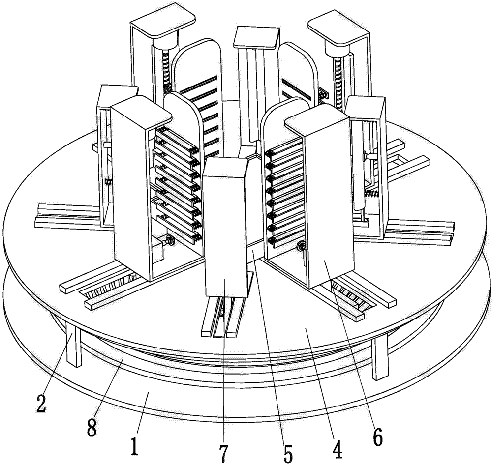
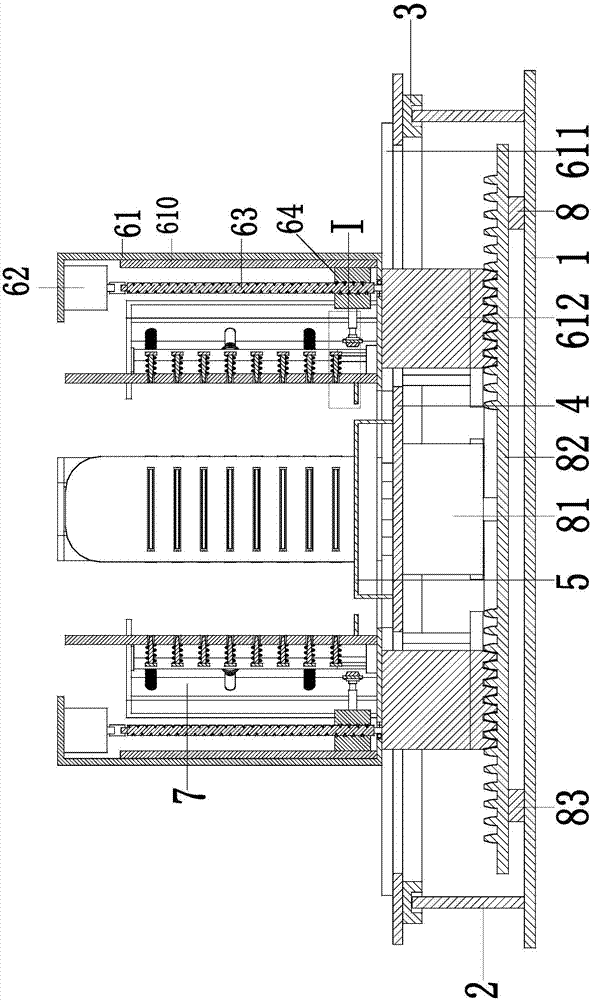
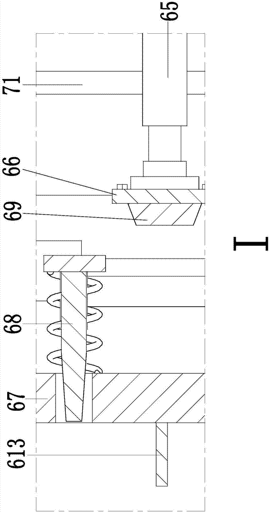
[0023] Such as Figure 1 to Figure 5 As shown, an automatic placement rack for toughened glass for curtain walls of high-rise buildings, including a bottom plate 1, four slide bars 2 are symmetrically installed on the bottom plate 1, and the upper ends of the four slide bars 2 are connected with chute 3 through sliding fit. 3 is installed on the adjustment plate 4, and the four sliding rods 2 cooperate with the chute 3 to support and assist the adjustment plate 4. The lower end of the adjustment plate 4 is equipped with an adjustment device 8, and the middle part of the upper end of the adjustment plate 4 is installed There is a placing table 5, and four walking grooves are symmetrically arranged on the adjusting plate 4, and a blocking device 6...


PUM


Abstract

The invention relates to a special tempered glass automatic placing rack for high-rise building curtain walls, which includes a bottom plate, an adjustment plate is installed on the bottom plate, an adjustment device is installed on the lower end of the adjustment plate, a walking groove is arranged on the adjustment plate, and a blocking device is arranged inside the walking groove, and A moving slot is arranged on the adjusting plate, and protective devices are arranged in the moving slots, and the adjusting device, the blocking device and the protective device cooperate with each other to complete the process of automatic adjustment of the glass placement rack. The invention can solve the need to manually select the corresponding glass placement rack according to different glass sizes in the placement process of the existing glass, and the existing glass placement rack can only fix the glass, and the mutual adsorption of the glass stacked together improves the The difficulty of loading and unloading the glass increases the labor intensity of the staff and reduces the work efficiency. The sharp corners of the glass are easy to cause injury to the staff, poor safety performance, poor stability and other problems.

Description

technical field [0001] The invention relates to the technical field of glass placement equipment, in particular to an automatic placement rack for toughened glass for curtain walls of high-rise buildings. Background technique [0002] With the progress and development of society, glass is widely used in high-rise building curtain walls and other fields, because glass has good perspective, light transmission, sound insulation and heat preservation, and is loved by people. Glass is fragile and has a smooth surface during transportation. The process of storage and storage is easy to cause glass breakage. The existing glass rack can only fix the proportion after processing, and the corners of the processed glass are relatively sharp and easy to scratch the staff. Together, they are easy to adsorb each other, which increases the difficulty of glass loading and unloading. The existing glass racks need to be moved by other mobile devices during the transportation process. When tran...

Claims


Application Information

Patent Timeline
IPC IPC(8): B25H3/04B65D85/48
CPCB25H3/04B65D85/48
Inventor 沈永根
Owner 安徽海之纳科技有限公司
Features
  • Generate Ideas
  • Intellectual Property
  • Life Sciences
  • Materials
  • Tech Scout
  • Unparalleled Data Quality
  • Higher Quality Content
  • 60% Fewer Hallucinations
Learn More