Tyre tread pattern structure for engine driven two-wheel vehicle

A technology for motorized two-wheeled vehicles and tread patterns, applied to tire treads/tread patterns, tire parts, vehicle components, etc. Rigidity and other issues to achieve the effect of improving wet grip performance, improving grip performance, and ensuring tread rigidity

Active Publication Date: 2017-09-15
CHENG SHIN RUBBER (XIAMEN) IND LTD
View PDF8 Cites 8 Cited by
  • Summary
  • Abstract
  • Description
  • Claims
  • Application Information

AI Technical Summary

Problems solved by technology

In order to ensure the grip performance of the tire when driving on wet ground, the tread is generally equipped with a low land ratio inclined groove pattern. The inclined groove pattern with a low land ratio has many drainage channels, but its ground contact surface is small. When driving, poor handling performance and poor driving stability
In order to meet the coexistence of dry and wet handling and grip performance, various studies have been carried out in the past, such as Image 6 As shown, the tread is configured with a positive "eight" slanted groove group 10' to improve the grip performance on wet ground. In addition, in order to exert the edge effect, an inverted "eight" slanted groove group 20' is properly configured in the direction of travel. The combination of the two is designed It will reduce the rigidity of the tread, reduce the handling stability when going straight and turning, and impair the safety when driving

Method used


Image

  • Tyre tread pattern structure for engine driven two-wheel vehicle
  • Tyre tread pattern structure for engine driven two-wheel vehicle
  • Tyre tread pattern structure for engine driven two-wheel vehicle

Examples


Embodiment approach

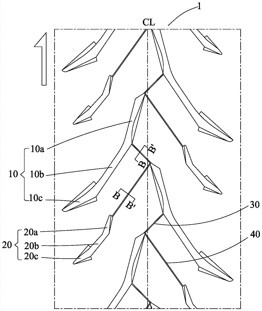
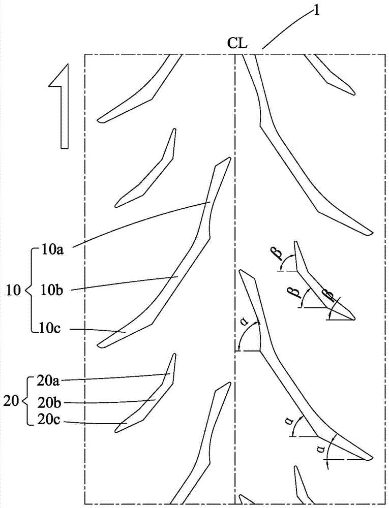
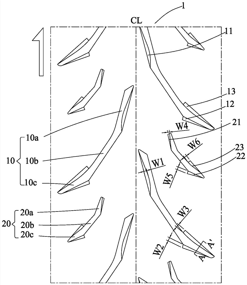
[0023] Such as Figure 1 to Figure 5 As shown, the present invention discloses a pneumatic tire tread pattern structure for two-wheeled motor vehicles. The transverse direction is the tire axial direction, the vertical direction is the tire circumferential direction, CL is the equatorial plane, and the arrow points to the tire driving direction.

[0024] Cooperate figure 2 As shown, the tire tread 1 is composed of several pattern units arranged symmetrically and staggered along the equatorial plane of the tire. Each pattern unit includes a main groove 10 and a secondary groove 20. The main groove 10 is inclined from the equatorial plane to the shoulder Extends and is composed of a first main groove 10a close to the equatorial plane, a third main groove 10c close to the shoulder, and a second main groove 10b connecting the first main groove 10a and the third main groove 10c, wherein The main grooves and the axial inclination angle α from near the equatorial plane to the shoulder ...


PUM


Abstract

The invention discloses a tyre tread pattern structure for an engine driven two-wheel vehicle. The structure consists of a plurality of pattern units which are arranged in a symmetrically staggered mode along the equatorial surfaces of tyres. Each pattern unit comprises a main pattern ditch and an auxiliary pattern ditch; each main pattern ditch consists of a first main pattern ditch close to the equatorial surface, a third main pattern ditch close to the tyre shoulder and a second main pattern ditch connected with the first main pattern ditch and the third main pattern ditch; each auxiliary pattern ditch consists of a first auxiliary pattern ditch away from the first main pattern ditch, a third auxiliary pattern ditch close to the tyre shoulder and a second auxiliary pattern ditch connected with the first auxiliary pattern ditch and the third auxiliary pattern ditch; and each main pattern ditch and the corresponding auxiliary pattern ditches are obliquely formed in a variable-angle mode in the axial direction from a position close to the equatorial surface to the tyre shoulder, the widths of the front ends and the tail ends of the pattern ditches are arranged by adopting a decrement way, and expansion grooves are additionally formed in the front ends and the tail ends of the main pattern ditches and the auxiliary pattern ditches. The manipulation performance and the ground grasping performance are achieved when the engine driven two-wheel vehicle runs on the dry and wet ground.

Description

Technical field [0001] The invention relates to a pneumatic tire for a two-wheeled vehicle, in particular to a tread pattern structure of a pneumatic tire for a two-wheeled vehicle. Background technique [0002] With the continuous improvement of domestic living standards, the market demand for large-displacement motorcycles for leisure and entertainment has increased year by year. Large-displacement motorcycles are favored by more and more consumers. The performance requirements are high, especially for the handling performance of the vehicle, the gripping ability of the tires and the stability of cornering. In the past, large-displacement motor vehicle tires, in order to ensure the handling performance of the tires when driving on dry ground, the tread is generally set with a higher land ratio inclined groove pattern (herein "land ratio" refers to the total area of ​​a certain area of ​​the tread Is s, the block area of ​​the region is a, then the ratio of the block area a of ...

Claims


Application Information

Patent Timeline
Patent Type & Authority Applications(China)
IPC IPC(8): B60C11/12B60C11/13
CPCB60C11/1204B60C11/1259B60C11/1272B60C11/13Y02T10/86
Inventor 陈秀雄
Owner CHENG SHIN RUBBER (XIAMEN) IND LTD
Why Eureka
Try Eureka