Eureka AIR delivers breakthrough ideas for toughest innovation challenges, trusted by R&D personnel around the world.

Roller structure for PET bottle conveying mechanism

A bottle conveying and roller technology, applied in the direction of conveyors, conveyor objects, rollers, etc., can solve the problems of difficult control of the speed of the main machine, unstable control of PET bottle conveying, etc., achieve stable rotation speed, avoid slippage, and realize cleaning effect

Inactive Publication Date: 2017-09-15
安徽沃兰朵电源技术有限公司
View PDF5 Cites 0 Cited by
  • Summary
  • Abstract
  • Description
  • Claims
  • Application Information

AI Technical Summary

Problems solved by technology

[0006] For the conveying mechanism of the automatic bottle loading machine, the chain conveying structure adopted, the conveying control of the PET bottle is unstable, and the speed of the main machine is not easy to control

Method used


Image

  • Roller structure for PET bottle conveying mechanism

Examples


Embodiment Construction

[0021] The following will clearly and completely describe the technical solutions in the embodiments of the present invention with reference to the accompanying drawings in the embodiments of the present invention. Obviously, the described embodiments are only some, not all, embodiments of the present invention. Based on the embodiments of the present invention, all other embodiments obtained by persons of ordinary skill in the art without creative efforts fall within the protection scope of the present invention.

[0022] In describing the present invention, it is to be understood that the terms "opening", "upper", "lower", "thickness", "top", "middle", "length", "inner", "surrounding" etc. Indicating orientation or positional relationship is only for the convenience of describing the present invention and simplifying the description, and does not indicate or imply that the components or elements referred to must have a specific orientation, be constructed and operated in a sp...


PUM


Abstract

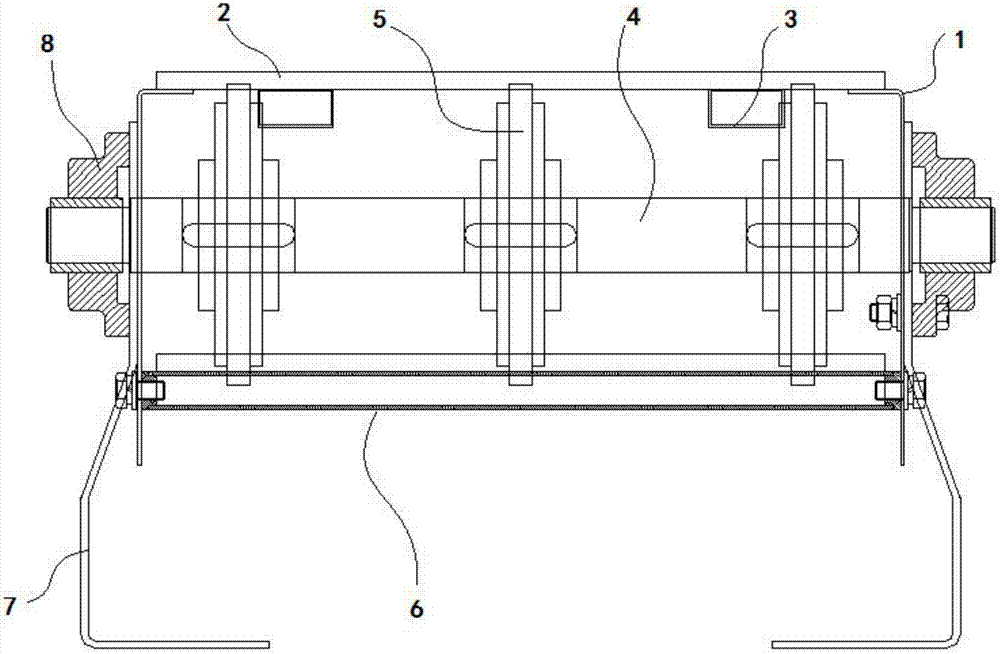
The invention discloses a roller structure used in a PET bottle conveying mechanism. It includes a roller shaft and a shaft seat. The roller shaft fixes several groups of sprockets side by side in the axial direction; the two ends of the roller shaft are equipped with shaft seats; the shaft seat is fixed on the side plate; one end of the side plate is fixed with a A top plate; a roller is fixed on one side of the side plate; a fixing seat is fixed on the other side of the side plate. The present invention realizes the transportation of the chain by adopting the sprocket wheel of elastic structure, improves the elastic stress strain, reduces the impact of the stress, and sets up the cleaning mechanism to clean the sprocket wheel to realize the cleaning of the mechanism, and adopts the roller and the chain The cooperation of the sprocket is used to stabilize the rotation rate of the sprocket and prevent the sprocket from slipping.

Description

technical field [0001] The invention belongs to the automatic technical field of bottle feeding machines for PET bottles, and in particular relates to a roller structure used for a PET bottle conveying mechanism. Background technique [0002] The modern conveyor system has higher requirements for dust prevention. For this reason, sprinklers and dust collection devices are installed at each transfer point, and windshields or windshields are installed along the belt conveyor. The system is composed of a single machine Yes, for operators and repairers who work in the whole system, they must not only base themselves on the stand-alone machine they are in charge of, but also understand the interrelationships between the systems. A stand-alone machine is composed of many components. Routine maintenance to keep it in good working condition can ensure the safe operation of the equipment; [0003] Generally, we will meet the forms of various operating conditions according to the use...

Claims


Application Information

Patent Timeline
Patent Type & Authority Applications(China)
IPC IPC(8): B65G39/02B65G45/10B65G23/04
CPCB65G39/02B65G23/04B65G45/10
Inventor 张燕
Owner 安徽沃兰朵电源技术有限公司
Why Eureka
Eureka Blog
Learn More