
An adjustable brushing tool

An adjustable and brushing technology, which is applied in the direction of construction and building construction, can solve the problems of not being able to carry out the length, improve work efficiency, and need to move the ladder, etc., to achieve convenient angle adjustment, convenient and fast positioning, and realization of fixing and Keep the effect

Inactive Publication Date: 2019-04-05
YANGTZE NORMAL UNIVERSITY
View PDF5 Cites 0 Cited by
  • Summary
  • Abstract
  • Description
  • Claims
  • Application Information

AI Technical Summary

Problems solved by technology

[0002] When carrying out interior decoration, it is usually necessary to paint the wall. The existing wall brushing device is generally a simple roller brush. Since the angle of the roller brush cannot be adjusted, it can only paint vertical walls or horizontal ceilings. For some inclined Walls or uneven walls or ceilings cannot be painted well
In addition, when painting higher walls or ceilings, operators often need to use climbing tool ladders and the like. After using the ladder to paint part of the wall, they also need to move the ladder to paint other parts of the wall. To change a place, you need to move the ladder, which is troublesome, time-consuming and labor-intensive, and it is not safe
[0003] The brushing tools in the prior art can neither adjust the length nor adjust the angle, which is very inconvenient to use and is not conducive to improving work efficiency

Method used


Image

  • An adjustable brushing tool
  • An adjustable brushing tool
  • An adjustable brushing tool

Examples


Embodiment Construction

[0021] The present invention will be further described in detail below in conjunction with the accompanying drawings and preferred embodiments.

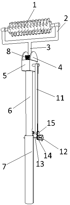
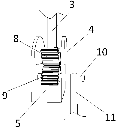
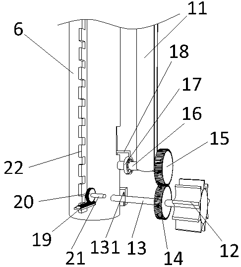
[0022] Such as Figure 1 to Figure 5 As shown, an adjustable brushing tool includes a brush head and a brush rod, the brush rod includes a fixed rod 6, and the fixed rod 6 is slidably sleeved with a movable rod 7; the brush head is connected to the fixed rod through an angle adjustment mechanism. The upper end of the rod 6; the fixed rod 6 is provided with a telescopic positioning mechanism; the fixed rod 6 is also provided with a switching mechanism; the brush head includes a connecting frame 2 and a roller brush 1; the roller brush 1 is installed on the The upper end of the connecting frame 2; the roller brush 1 is sheathed on the horizontal bar and can rotate around the horizontal bar; the lower end of the connecting frame 2 is detachably connected with the first half gear 8 through the vertical bar 3; the lower end of the vertica...


PUM


Abstract

The invention discloses an adjustable brushing tool. The adjustable brushing tool comprises a brushing head and a brushing rod, wherein the brushing rod comprises a fixed rod and a movable rod which are in bell socket in a sliding manner; the brushing head is connected to the upper end of the fixed rod through an angle adjusting mechanism; the fixed rod is internally provided with a telescopic positioning mechanism; a switching mechanism is further arranged on the fixed rod; the angle adjusting mechanism comprises a gear box, and the gear box is internally provided with a first half gear and a second half gear which are engaged; a second horizontal rotating shaft is arranged on the second half gear, a first belt pulley is arranged on the second horizontal rotating shaft, and a third horizontal rotating shaft is connected onto the fixed rod in a rotating manner; the first belt pulley and a second belt pulley are driven through a belt; the telescopic positioning mechanism comprises a clamping strip, a clamping shaft and a rack; the rack is engaged with a second gear, and a fourth horizontal rotating shaft is arranged on the second gear; the switching mechanism comprises a hollow shaft; a third gear capable of being engaged with the first gear is arranged on the stretching end of the hollow shaft; the hollow shaft can slide towards the interior of the fixed rod and is connected with the fourth rotating shaft in an inserted manner, so that the hollow shaft can drive the fourth horizontal rotating shaft to rotate.

Description

technical field [0001] The invention relates to a painting tool for painting walls or ceilings. Background technique [0002] When carrying out interior decoration, it is usually necessary to paint the wall. The existing wall brushing device is generally a simple roller brush. Since the angle of the roller brush cannot be adjusted, it can only paint vertical walls or horizontal ceilings. For some inclined Uneven walls or uneven walls or ceilings cannot be painted well. In addition, when painting higher walls or ceilings, operators often need to use climbing tool ladders and the like. After using the ladder to paint part of the wall, they also need to move the ladder to paint other parts of the wall. To change a place, it is necessary to move the ladder, which is troublesome to use, time-consuming and labor-intensive, and it is not safe. [0003] The brushing tools in the prior art can neither adjust the length nor adjust the angle, which is very inconvenient to use and is ...

Claims


Application Information

Patent Timeline
Patent Type & Authority Patents(China)
IPC IPC(8): E04F21/06
CPCE04F21/06
Inventor 欧阳紫滕王涛
Owner YANGTZE NORMAL UNIVERSITY
Learn More