
Lock catch structure and magnetic lock

A lock and lock core technology, applied in the field of magnetic locks, can solve the problems of locks not working normally, high risk of being unlocked, cumbersome operation, etc., and achieve the effect of not being easy to be cracked, simple structure, and simple unlocking method

Active Publication Date: 2017-09-15
HANGZHOU CCRFID MICROELECTRONICS
View PDF7 Cites 4 Cited by
  • Summary
  • Abstract
  • Description
  • Claims
  • Application Information

AI Technical Summary

Problems solved by technology

[0003] With the existing one-piece buckle structure, it is necessary to use a T-shaped hexagonal screwdriver to lock or open the screw between the one-piece buckle and the wristband during use, and the operation is cumbersome
Moreover, after long-term tightening and opening actions between the integrated buckle screw and the wrist strap nut, the sliding teeth are prone to damage, which will cause the entire buckle to fail to work normally.
The unlocking method of this lock structure is also easy to learn, and the risk of being unlocked is high

Method used


Image

  • Lock catch structure and magnetic lock
  • Lock catch structure and magnetic lock
  • Lock catch structure and magnetic lock

Examples


Embodiment Construction

[0028] The above and other technical features and advantages of the present invention will be clearly and completely described below in conjunction with the accompanying drawings. Apparently, the described embodiments are only some of the embodiments of the present invention, not all of them.

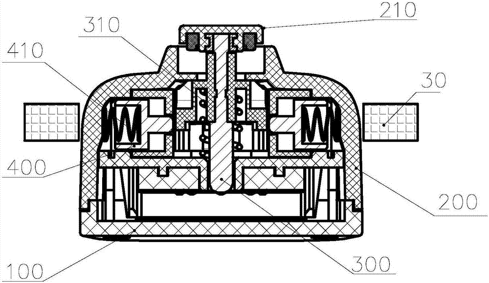
[0029] see Figure 3 to Figure 6 , The lock structure provided by Embodiment 1 of the present invention includes a bottom lock case 100 , a lock cover 200 fixed on the lock bottom case 100 , and a lock cylinder 300 located between the lock cover 200 and the lock bottom case 100 .

[0030] see image 3 with Figure 4 , one end of the lock cylinder 300 is movably connected with the lock cover 200, and the other end is suspended above the lock bottom case 100 through the first elastic device 310, and a preset distance is maintained between the lock bottom case 100, and the preset distance is used Insert the movable end 10 of the device to be locked. One end of the lock cylinder 300 can ...


PUM


Abstract

The invention discloses a lock catch structure and a magnetic lock. The lock catch structure comprises a lock bottom shell, a lock upper cover fixed to the lock bottom shell, and a lock cylinder located between the lock upper cover and the lock bottom shell. One end of the lock cylinder is movably connected with the lock upper cover. The other end of the lock cylinder is suspended above the lock bottom shell through a first elastic device, the preset distance is formed between the other end of the lock cylinder and the lock bottom shell, and therefore the movable end of a to-be-locked device can be inserted in the preset distance. The lock cylinder is further provided with a clamping structure. The lock upper cover is provided with pins. One end of each pin is connected with the lock upper cover through a second elastic device, and the other end of each pin is matched with the clamping structure. The magnetic lock comprises the lock catch structure and an unlocking magnet, the structure is simple, using is convenient, the unlocking manner is simple but ingenious, and cracking is not easy.

Description

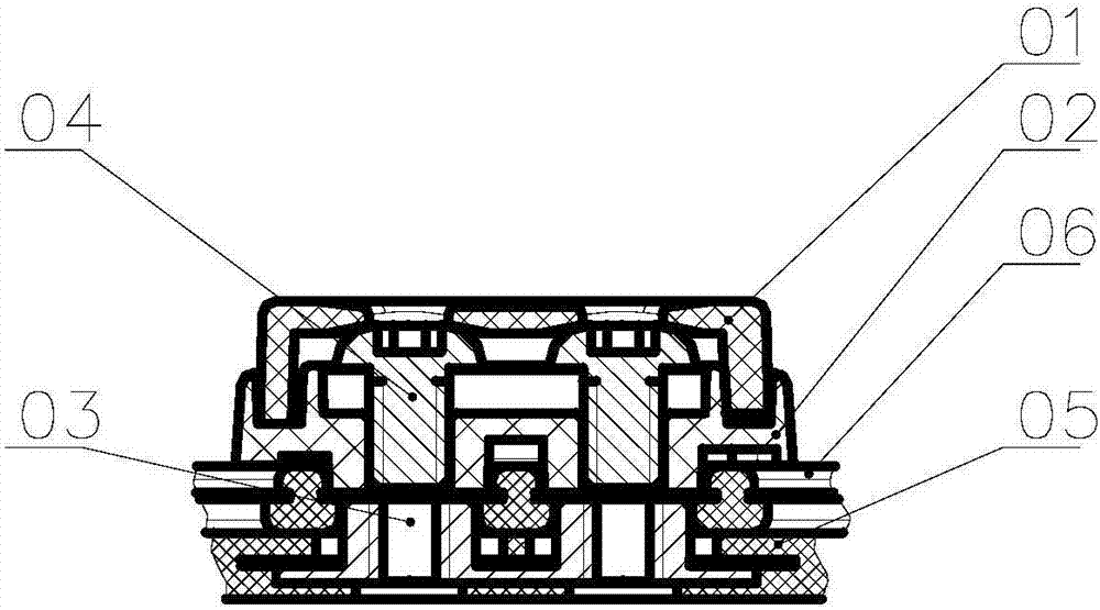
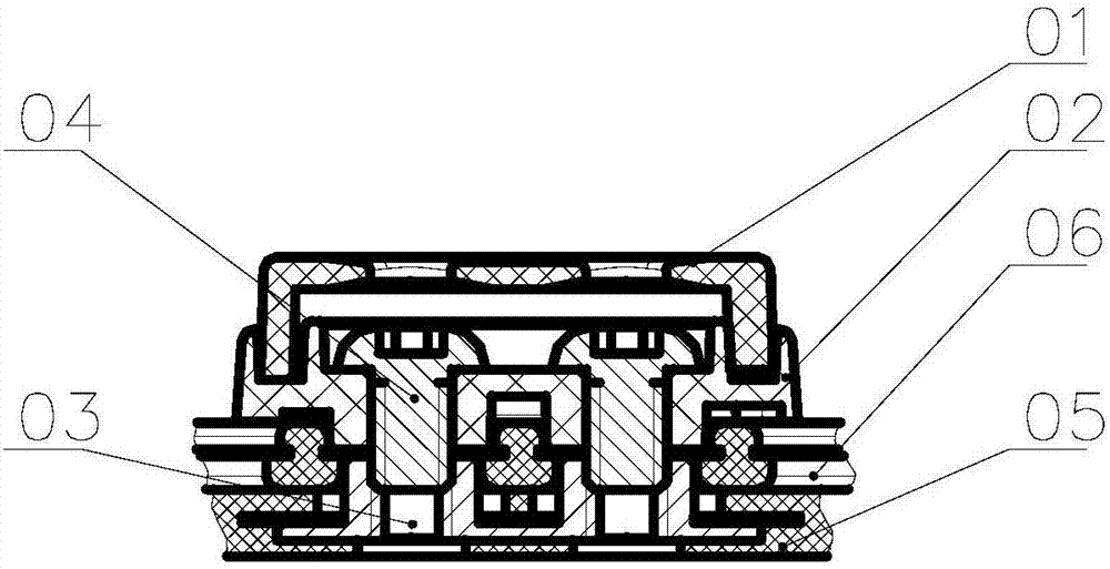
technical field [0001] The invention relates to the technical field of locks, in particular to a lock structure and a magnetic lock comprising the lock structure. Background technique [0002] The existing lock structure generally adopts the integrated buckle lock mode. Taking the wristband lock as an example, its structure when it is in the unlocked state is as follows: figure 1 As shown, it includes an integrated button upper cover 01, an integrated button lower cover 02, a nut 03 and a screw 04, wherein the fixed wrist strap 05 is fixed on the integrated lower cover 02, and the nut 03 is installed on the movable wrist strap 06. The locking method is to place the movable wristband 06 on top of the fixed wristband 05 and then install the integrated buckle on the outside of the nut 03 on the movable wristband 06, and then use a T-shaped hexagonal screwdriver to screw the screw 04 inside the integrated buckle Lock with the nut 03 on the wrist strap, such as figure 2 As sho...

Claims


Application Information

Patent Timeline
Patent Type & Authority Applications(China)
IPC IPC(8): E05B73/00E05B47/00A44C5/20A44B11/25
CPCA44B11/2573A44C5/20E05B47/0038E05B73/00
Inventor 陈晓初邵龙炬
Owner HANGZHOU CCRFID MICROELECTRONICS
Learn More