Installation method of width adjustable assembly type wood-plastic door pocket

An installation method and adjustable technology, applied in the direction of window/door frame, frame fixing, etc., can solve the problems of non-adjustable size, complicated installation operation, scrapped parts, etc., and achieve the effect of reducing loss, convenient and simple operation, and reducing economic loss

Inactive Publication Date: 2017-09-15
NORTHEAST FORESTRY UNIVERSITY
View PDF10 Cites 1 Cited by
  • Summary
  • Abstract
  • Description
  • Claims
  • Application Information

AI Technical Summary

Problems solved by technology

[0005] The purpose of the present invention is to solve the problem that the existing wood-plastic door cover pollutes the environment, the size cannot be adjusted during the installation process, the installation operation is complicated, and the replacement door cover is destructive and lossy when disassembled, and the disassembled parts are scrapped as a whole and cannot be recycled. problem, but provides a width-adjustable assembly wood-plastic door cover installation method

Method used


Image

  • Installation method of width adjustable assembly type wood-plastic door pocket
  • Installation method of width adjustable assembly type wood-plastic door pocket
  • Installation method of width adjustable assembly type wood-plastic door pocket

Examples


specific Embodiment approach 1

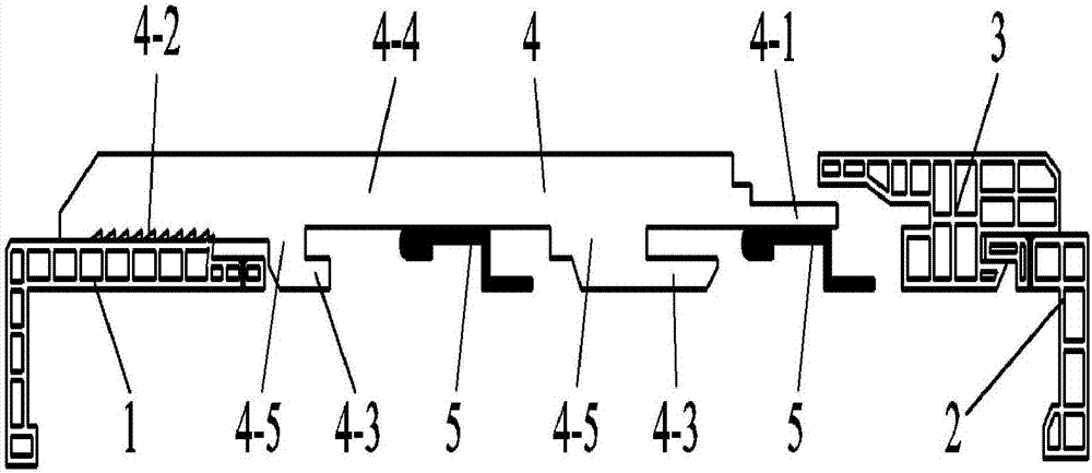
[0047] Specific Embodiment 1: Combining Figure 8 , Figure 9 and Figure 10 Describe this embodiment, the installation method of the width-adjustable assembled wood-plastic door cover of this embodiment is carried out according to the following steps:

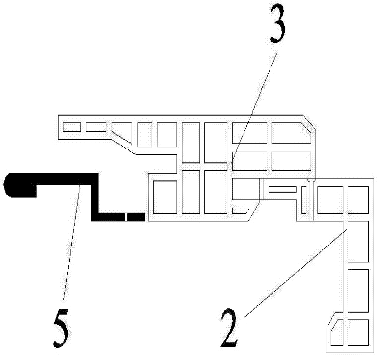
[0048] 1. Firstly, the L-shaped profile a1 and the L-shaped profile b2 are fixedly connected to the edge of the doorway wall, and the L-shaped profile a1 is provided with anti-reverse components;

[0049] 2. Fix the Z-shaped connector 5 in proportion to the wall between the L-shaped profile a1 and the L-shaped profile b2;

[0050] 3. Insert the I-shaped pluggable profile 3 onto the L-shaped profile b2;

[0051] 4. Finally, the adjustable plug-in part 4 is inserted into the I-shaped pluggable profile 3 in order, and then inserted into the Z-shaped connector 5, and then covered on the L-shaped profile a1; the adjustable plug-in part 4 A non-return fitting part 4-2 is provided to cooperate and connect with the non-return part...

specific Embodiment approach 2

[0052] Specific Embodiment 2: Combining figure 1 , figure 2 , image 3 , Figure 4 , Figure 5 and Figure 6 Describe this embodiment, the difference between this embodiment and specific embodiment 1 is that the structure of the L-shaped profile a1 has at least one long side and one short side in its section, and the long side and the short side are connected at one end , the end of the long side far away from the short side is provided with a non-return component, and the L-shaped profile a1 also has at least one connecting part, and the connecting part can be fixedly connected to the wall through a connecting piece, so The connecting portion is located on the long side, the short side or the extension of the long side and the short side; the structure of the L-shaped profile b2 has at least two sides in its section, and the two sides are connected at one end and The length of the two sides is similar, and the L-shaped profile b2 also has at least one connecting part, w...

specific Embodiment approach 3

[0054] Embodiment 3: Combining figure 1 and figure 2 This embodiment is described. The difference between this embodiment and the specific embodiment 1 or 2 is that the non-return part and the non-return matching part are barb non-return part, convex anti-return part, magnetic non-return part and frictional non-return part. One or a combination of several parts; It should be noted that the door frame width can be effectively fixed by anti-reverse components such as barb anti-reverse parts or magnetic components.


PUM


Abstract

The invention discloses an installation method of a width adjustable assembly type wood-plastic door pocket, belongs to the technical field of woo-plastic door pocket installation, and particularly relates to the field of installation methods of width adjustable assembly type wood-plastic door pockets. The invention aims to solve the problems that the environment is polluted by existing wood-plastic door pockets, the dimensions in the installation process are unchangeable, the installation operation is complex and the door pockets are destructive and damaged and disassembled components are integrally scrapped and cannot be recycled when the door pockets are changed and disassembled. The installation method of the width adjustable assembly type wood-plastic door pocket disclosed by the invention comprises the following steps: firstly fixedly connecting an L-shaped sectional material a1 and an L-shaped sectional material b2 with a door opening wall body, then hammering into a group of Z-shaped connecting pieces, connecting an H-shaped inserted sectional material 3 with the L-shaped sectional material b2 in an inserted manner, and then connecting an inserting and connecting part 4-1 of an adjustable inserted cover component 4 with the inserting and connecting matching part of the H-shaped inserted sectional material 3 and the circular arc-shaped bulge part of a Z-shaped connecting piece 5 in the inserted manner so as to realize rapid installation of the door pocket.

Description

technical field [0001] The invention belongs to the technical field of installation of wood-plastic door pockets, in particular to the field of installation methods of wood-plastic door pockets with adjustable width. Background technique [0002] As a waterproof and environmentally friendly product, wood-plastic doors have already occupied a certain share in the market. The overall extrusion process is mostly used in the production of wood-plastic doors, but the dimensional stability of the door structure, the control of the weight of the door body, and the decorative effect of the surface of the door panel are limited to a certain extent. In addition, in the field of construction engineering, due to construction accuracy and other reasons, the thickness of walls in different rooms of the same building is not exactly the same, and even the thickness of walls in different positions in the same indoor space is sometimes not exactly the same. The installation of door products ...

Claims


Application Information

Patent Timeline
IPC IPC(8): E06B1/34E06B1/52E06B1/32E06B1/60
CPCE06B1/32E06B1/34E06B1/52E06B1/60
Inventor 王清文宗广功房轶群吕艳丽
Owner NORTHEAST FORESTRY UNIVERSITY
Why Eureka
Try Eureka