Multiwave time domain matching method and device

A matching method and time-domain technology, applied in the field of seismic exploration, can solve problems such as poor adaptability

Active Publication Date: 2017-09-15
BC P INC CHINA NAT PETROLEUM CORP +1
View PDF6 Cites 11 Cited by
  • Summary
  • Abstract
  • Description
  • Claims
  • Application Information

AI Technical Summary

Problems solved by technology

[0007] The embodiment of the present invention provides a multi-wave time-domain matching method to solve the technical problem that the P-S wave time-matching method in the prior art has poor adaptability to large changes in the P-S wave velocity ratio

Method used


Image

  • Multiwave time domain matching method and device
  • Multiwave time domain matching method and device
  • Multiwave time domain matching method and device

Examples


example 1

[0087] Example 1. We build a depth domain model and convert it to the corresponding longitudinal wave and converted wave time domain according to the longitudinal wave and shear wave velocity, and obtain the corresponding longitudinal wave and converted wave data as Figure 6 shown. The corresponding P-wave time difference and velocity ratio distribution in the P-wave time domain are as follows: Figure 7 shown. In order to verify the stability of the multi-wave time matching method of this application, random noise is added to the original data, so that the signal-to-noise ratio is 2:1, such as Figure 8 shown. Applying the multi-wave time matching method of this application, we can obtain the time difference of compressional and shear waves and the inversion speed corresponding to the noisy data, such as Figure 9 shown. It can be seen from the figure that this method has good stability for the data containing strong noise, the obtained time difference conforms to the mo...

example 2

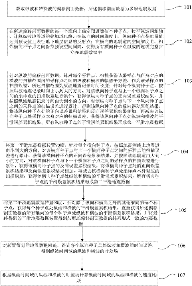
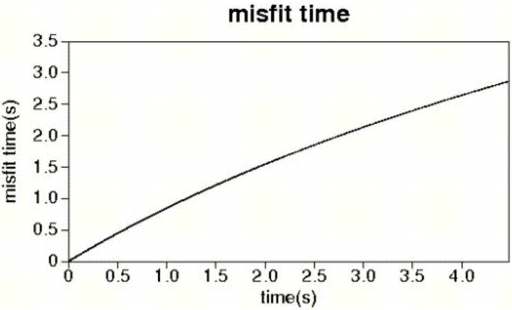
[0088] Example 2. We use the actual processed longitudinal wave data ( Figure 10 ) and converted wave data to test the method ( Figure 11 ). Layer flattening is performed on the longitudinal wave data, and the distribution of the seed points in the section is obtained as follows: Figure 12 Indicated by the white line. Using the multi-wave time matching method of this application, the time difference of the longitudinal and transverse waves and the velocity ratio field can be obtained as Figure 13 shown. According to the time difference of the longitudinal and transverse waves, the converted wave is time-corrected, and the results are as follows Figure 14 , it can be seen that the longitudinal wave and the converted wave can get good automatic time matching, avoiding artificial interference.

[0089] Based on the same inventive concept, an embodiment of the present invention also provides a multi-wave time matching device, as described in the following embodiments. S...


PUM


Abstract

The embodiment of the invention provides a multiwave time domain matching method and device. The method comprises steps of determining preset numbers of seed points in each dimensional direction of deviation profile data; for the deviation profile data of longitudinal waves, acquiring smoothing error accumulation results of the longitudinal waves and the transverse waves at the seed points, wherein the smoothing error accumulation results of all longitudinal seed points form first smoothing earthquake data; transposing the first smoothing earthquake for 90 degrees to acquire smoothing error accumulation results of the longitudinal waves and transverse waves at the seed points, wherein the smoothing error accumulation results of all transverse seed points form second smoothing earthquake data; transposing the second smoothing earthquake for 90 degrees, and acquiring smoothing error accumulation results of the longitudinal waves and the transverse waves at each of seed points in other dimensional directions except for longitudinal and transverse directions; backtracking earthquake data obtained through the transposition to obtain time difference field of the longitudinal waves and the transverse waves of the longitudinal wave time domain; and according to the time difference field, calculating speed ratios of the longitudinal waves and the transverse waves of the longitudinal wave time domain.

Description

technical field [0001] The invention relates to the technical field of seismic exploration, in particular to a multi-wave time-domain matching method and device. Background technique [0002] Since multi-wave seismic data contains more abundant subsurface information, it has shown good application prospects in inversion of reservoir properties and oil and gas prediction. Multi-wave seismic exploration technology has been widely used since the 1990s. Compared with the reservoir information that cannot be accurately identified by single longitudinal wave exploration, multi-wave seismic data can preserve and mine the reflection information of longitudinal waves and converted waves. and so on have a wide range of applications. Among them, the research on the matching method of P- and S-waves in multi-wave seismic data is a key issue that plagues the processing and subsequent inversion of multi-wave seismic data. Because of the difference in the propagation speeds of the longit...

Claims


Application Information

Patent Timeline
Patent Type & Authority Applications(China)
IPC IPC(8): G01V1/30
CPCG01V1/303G01V1/305G01V2210/6222
Inventor 陈双全靳松李向阳
Owner BC P INC CHINA NAT PETROLEUM CORP
Why Eureka
Try Eureka