Multi-parameter collision waveform quality evaluation method

A waveform quality and evaluation method technology, applied in complex mathematical operations, electrical digital data processing, special data processing applications, etc., can solve the problems of time-consuming and expensive collision waveforms, strong randomness of evaluation results, etc., to avoid large randomness. , to avoid the effect of a single indicator

Inactive Publication Date: 2017-09-15
JILIN UNIV
View PDF3 Cites 10 Cited by
  • Summary
  • Abstract
  • Description
  • Claims
  • Application Information

AI Technical Summary

Problems solved by technology

[0005] The technical problem to be solved by the present invention is to overcome the time-consuming and money-consuming problems in judging the pros and cons of

Method used


Image

  • Multi-parameter collision waveform quality evaluation method
  • Multi-parameter collision waveform quality evaluation method
  • Multi-parameter collision waveform quality evaluation method

Examples


Embodiment 1

[0133] This embodiment only evaluates the quality of the collision waveform of a CHEVROLET CRUZE model. The evaluation steps are as follows:

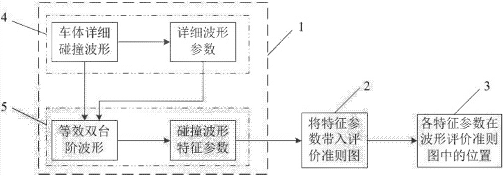
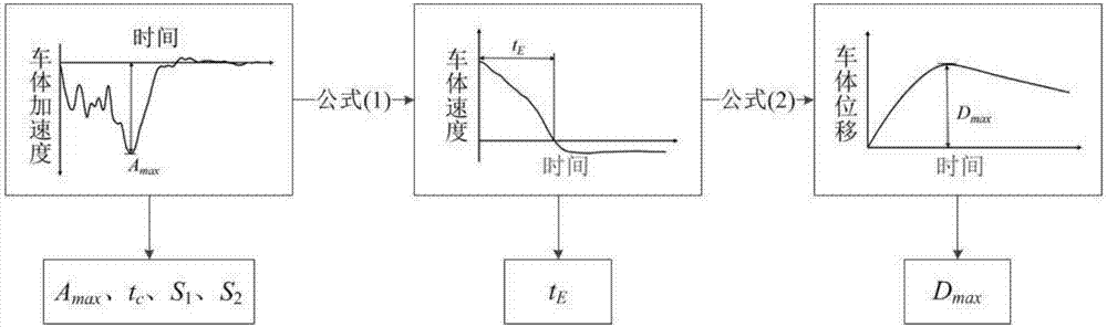
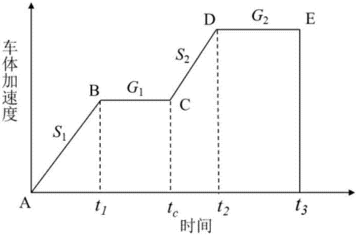
[0134] 1. See figure 1 , input the collision waveform collected from the lower end of the B-pillar of the CHEVROLET CRUZE model into the signal processing module 1. refer to figure 2 , the detailed waveform processing module 4 in the signal processing module 1 uses formulas (1) and (2) to perform mathematical calculations on the collision waveform to obtain the vehicle body collision velocity-time curve and displacement-time curve. Further, extract the peak A from the collision waveform max , and based on experience, the time point corresponding to the trough between 0.02s and 0.03s on the collision waveform curve is the engine collision time t C ,, extract the slope between the origin and the first peak point on the collision waveform curve as S 1 , extracting the slope of the curve before the largest peak on the collision wavefo...

Embodiment 2

[0140] This embodiment only evaluates the quality of the collision waveform of a HYUNDAI ELANTRA model, and the specific implementation steps are the same as those in Embodiment 1. refer to Figure 8 , is the evaluation result diagram of the waveform, from which we can find the peak value A of the collision waveform max Outside the three-star boundary, it indicates that the value is poor; the engine collision time t C and engine front end collision space D 1 The value of is between the three-star boundary line and the four-star boundary line, which is relatively close to the three-star line, indicating that these two parameters need to be further optimized; the values ​​of the step ratio i and the energy absorption density α are close to the four-star boundary line, indicating that these two values ​​​​have to be further optimized space; the height of the first step G 1 and width ratio w are close to the five-star line, indicating that these two values ​​are relatively good...


PUM


Abstract

The invention discloses a multi-parameter collision waveform quality evaluation method and aims to solve the problems of time and money consuming during judgment of collision waveform quality and relatively strong randomness of an evaluation result in the prior art. The method comprises the steps that 1) a detailed waveform processing module obtains detailed waveform parameters through a detailed collision waveform of a vehicle body: (1) the detailed waveform processing module obtains a speed-time curve; (2) the detailed waveform processing module obtains a displacement-time curve; and (3) empirical parameters are extracted from the detailed waveform; 2) an equivalent dual-step waveform simplification module simplifies the detailed collision waveform of the vehicle body and obtains feature parameters; 3) a multi-parameter collision waveform evaluation criterion diagram is established; and 4) a signal output module gives out the evaluation result, namely, a central processing module (2) stores collision waveform feature parameter values obtained by a signal processing module (1) into the multi-parameter collision waveform evaluation criterion diagram and outputs the criterion diagram with the collision waveform parameter values to the signal output module (3), so that the evaluation result is obtained.

Description

technical field [0001] The present invention relates to a kind of evaluation method of automobile collision waveform, more specifically, the present invention relates to a kind of multi-parameter collision waveform quality evaluation method using the characteristic parameter of frontal collision waveform as index. Background technique [0002] Crash waveform is an important and easy-to-obtain response characteristic in vehicle collision, an important content of frontal crash crashworthiness design, and an important engineering parameter in the matching process of restraint system. Frontal collision waveform can not only be used to measure the severity of vehicle frontal collision, but more importantly, collision waveform is closely related to occupant injury. Different crash waveforms reflect different car body structure characteristics, so the evaluation of crashworthiness of car body structures is often carried out based on crash waveforms. Equivalent Dual-trapezia wave (...

Claims


Application Information

Patent Timeline
IPC IPC(8): G06F17/50G06F17/18
CPCG06F17/18G06F30/20
Inventor 张君媛王丹琦武栎楠倪滢滢刘茜房强李仲玉郭强纪梦雪
Owner JILIN UNIV
Why Eureka
Try Eureka