
Zero loss depth current-limiting protection device based on head wave breaking technology

A protection device and deep current limiting technology, applied in the direction of emergency protection circuit device for limiting overcurrent/overvoltage, emergency protection circuit device, protection that responds to overcurrent, etc., can solve the problem of rising investment costs, electric power Reduce, active and reactive power loss and other problems, to achieve the effect of improving mechanical life and reliability, reducing breaking capacity, and improving breaking capacity

Inactive Publication Date: 2017-09-15
安徽恒凯电力保护设备有限公司
View PDF8 Cites 6 Cited by
  • Summary
  • Abstract
  • Description
  • Claims
  • Application Information

AI Technical Summary

Problems solved by technology

[0003] Facing the increasingly serious problem of short-circuit current exceeding the standard, many enterprises use high-impedance transformers to limit the short-circuit current of the system, but increasing the impedance of the transformer does not finally solve the problem of current limiting depth. Rising investment costs
[0004] The use of ordinary series current-limiting reactors does not fundamentally solve the problem of current-limiting depth, and at the same time brings disadvantages such as active and reactive power loss, bus voltage drop, and leakage magnetic field. Generators, transformers and other major electrical equipment are damaged due to winding deformation under the impact of huge short-circuit current, and catastrophic accidents occur
[0005] At present, the explosive large-capacity high-speed breaking device and the reactor used in the market are operated in parallel. Although the problems of active and reactive power loss, voltage drop, and leakage magnetic field of the reactor are solved, when a short-circuit fault occurs, the primary components of the reactor will operate. After putting into use, it needs to work for a long time before replacing the equipment, and the reactance rate of the reactor is limited, which does not solve the problem of current limiting depth

Method used


Image

  • Zero loss depth current-limiting protection device based on head wave breaking technology
  • Zero loss depth current-limiting protection device based on head wave breaking technology
  • Zero loss depth current-limiting protection device based on head wave breaking technology

Examples


Embodiment Construction

[0039] The following will clearly and completely describe the technical solutions in the embodiments of the present invention with reference to the accompanying drawings in the embodiments of the present invention. Obviously, the described embodiments are only some, not all, embodiments of the present invention. Based on the embodiments of the present invention, all other embodiments obtained by persons of ordinary skill in the art without creative efforts fall within the protection scope of the present invention.

[0040] In describing the present invention, it is to be understood that the terms "opening", "upper", "lower", "thickness", "top", "middle", "length", "inner", "surrounding" etc. Indicating orientation or positional relationship is only for the convenience of describing the present invention and simplifying the description, and does not indicate or imply that the components or elements referred to must have a specific orientation, be constructed and operated in a sp...


PUM


Abstract

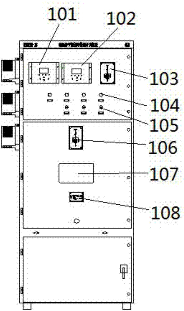
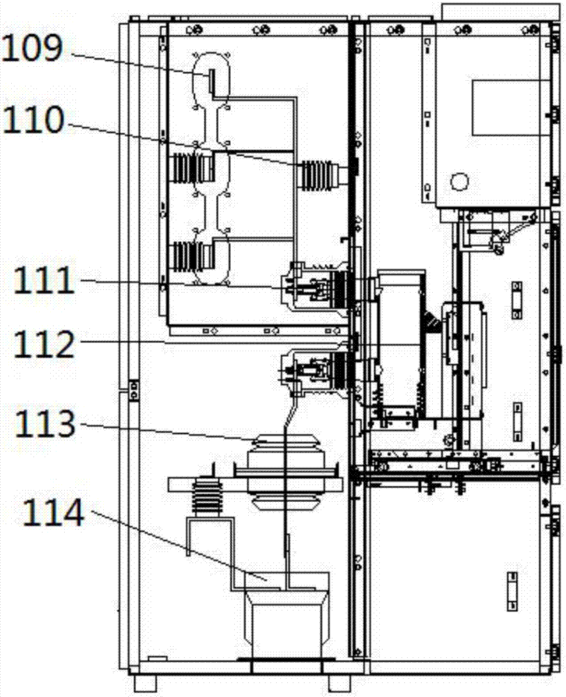
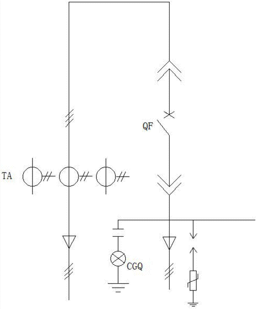
The invention discloses a zero-loss deep current-limiting protection device based on first-wave breaking technology, which includes a protection device body and high-speed switches distributed inside the protection device body; device, display and control, indicator light, button, analog plate, observation window and nameplate, and the inner side of the protection device body is provided with a through-bus bar, a supporting insulator, a quick switch, a first current transformer, a second current transformer and two contact boxes , wherein the through busbar is connected to one of the contact boxes through the supporting insulator, the other contact box is connected to the second current transformer through the first current transformer, and the two contact boxes are connected through a fast switch. The invention has fast action speed, strong breaking capacity, good current limiting effect of the current-limiting reactor, no energy loss, no voltage drop, and no leakage magnetic field, long service life, reliable performance, small action dispersion, and no switching on. rebound.

Description

technical field [0001] The invention belongs to the field of current limiting protection, in particular to a zero-loss deep current limiting protection device based on the first wave breaking technology. Background technique [0002] When a short-circuit fault occurs in the power system, the short-circuit current is generally more than ten times the rated current, which causes great harm to electrical equipment such as transformers, generators, circuit breakers, and transmission lines. The capacity is below 40kA, and the breaking time needs tens of milliseconds. With the development and growth of various types of power-consuming enterprises, the power consumption load has risen sharply, and the capacity of the main transformer has also increased accordingly. The short-circuit current faced by the power grid system of various enterprises has approached and reached the maximum use limit of the load vacuum circuit breaker. The load-side vacuum circuit breaker Insufficient brea...

Claims


Application Information

Patent Timeline
Patent Type & Authority Applications(China)
IPC IPC(8): H02H3/08H02H9/02H02H7/06H02H7/22H01H33/666
CPCH02H3/08H01H33/666H02H7/06H02H7/22H02H9/02H02H9/021
Inventor 王善立姜坛
Owner 安徽恒凯电力保护设备有限公司
Learn More