
Battery charging control circuit

A technology for controlling circuits and battery charging, applied in battery circuit devices, circuit devices, current collectors, etc., can solve problems such as inability to control autonomously and easily damage batteries.

Inactive Publication Date: 2017-09-15
OPTIMUM BATTERY CO LTD
View PDF8 Cites 2 Cited by
  • Summary
  • Abstract
  • Description
  • Claims
  • Application Information

AI Technical Summary

Problems solved by technology

The existing battery charging control circuit directly charges the battery with the maximum power at the beginning, which cannot be controlled independently and is easy to damage the battery

Method used


Image

  • Battery charging control circuit
  • Battery charging control circuit
  • Battery charging control circuit

Examples


Embodiment Construction

[0022] In order to make the objectives, technical solutions and beneficial technical effects of the present invention clearer, the technical solutions in the embodiments of the present invention will be clearly and completely described below in conjunction with the accompanying drawings in the embodiments of the present invention. Obviously, the described implementation The form is only a part of embodiments of the present invention, not all of them. Based on the implementation manners in the present invention, all other implementation manners obtained by persons of ordinary skill in the art without making creative efforts belong to the scope of protection of the present invention.

[0023] When an element is referred to as being "connected to" another element, it can be directly connected to the other element or intervening elements may also be present. Unless otherwise defined, all technical and scientific terms used herein have the same meaning as commonly understood by one...


PUM


Abstract

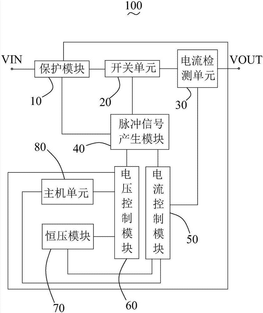
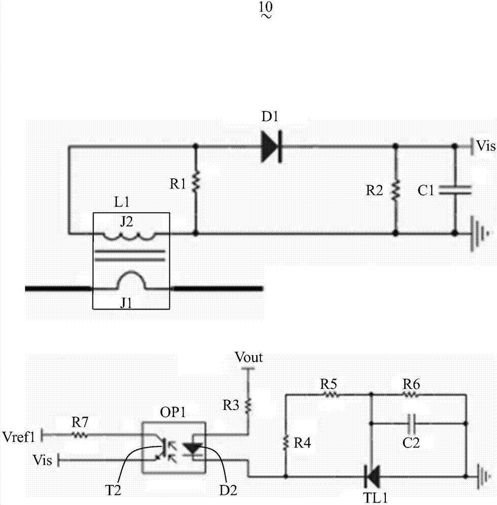
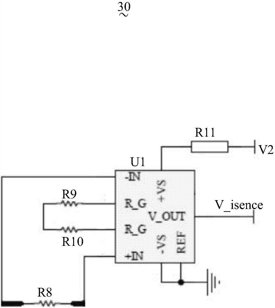
The invention discloses a battery charging control circuit, which comprises a protection module, a switch unit, a current detection unit, a pulse signal generation module, a current control module, a voltage control module, a constant voltage module and a host unit. The protection module is connected with a total input end, the switch unit, a total output end and the pulse signal generation module; the switch unit is connected with the current detection unit and the pulse signal generation module; the current control module is connected with the total output end and the current control module; the pulse signal generation module is connected with the current control module and the voltage control module; the current control module is connected with the constant voltage module and the host unit; and the voltage control module is connected with the constant voltage module, the host unit and the total output end.

Description

【Technical field】 [0001] The invention relates to the technical field of charging circuits, in particular to a battery charging control circuit. 【Background technique】 [0002] The production and use of batteries require a series of charging and discharging steps such as formation and capacity separation to form finished batteries. The formation of batteries refers to the initial charging of newly produced batteries. "Formation" means "transformation", using chemical and electrochemical reactions to convert the plates into positive and negative plates with electrochemical characteristics. This process is an important link that affects the life of the battery. Therefore, the requirements for the charging control circuit of the battery are very strict. Battery formation is usually divided into two stages: constant current charging and constant voltage charging, that is, first use small current trickle charging to make the battery terminal voltage reach the end-of-discharge vo...

Claims


Application Information

Patent Timeline
Patent Type & Authority Applications(China)
IPC IPC(8): H02J7/00
CPCH02J7/0077
Inventor 梁柱陈贵华饶睦敏李瑶
Owner OPTIMUM BATTERY CO LTD
Learn More