
A control system and control method for an intelligent vacuum degasser

A vacuum degassing and control system technology, applied in the field of degassing, can solve problems such as high energy consumption, water pump cavitation bearing wear, and inaccurate control, so as to shorten the debugging time, improve heat exchange efficiency, and save labor costs Effect

Active Publication Date: 2018-08-17
北京德安源环境科技发展有限公司
View PDF7 Cites 1 Cited by
  • Summary
  • Abstract
  • Description
  • Claims
  • Application Information

AI Technical Summary

Problems solved by technology

Because there is a large amount of gas in the water circulation system, if it is not removed, the system is prone to air resistance, which will cause poor circulation and uneven heating and cooling of the local or entire system, and cause damage to the equipment and pipelines in the system
At the same time, due to the dissolved oxygen in the water, the terminal equipment such as heating (refrigeration) equipment, pipes and steel radiators are corroded, perforated, and leaked, which directly affects the safety of the entire system.
At the same time, the gas in the system will cause the cavitation of the water pump and the wear of the bearing and generate noise in the system pipe network
[0003] Existing vacuum degassers are generally controlled by time or liquid level, which have defects such as high energy consumption and inaccurate control

Method used


Image

  • A control system and control method for an intelligent vacuum degasser
  • A control system and control method for an intelligent vacuum degasser
  • A control system and control method for an intelligent vacuum degasser

Examples


Embodiment

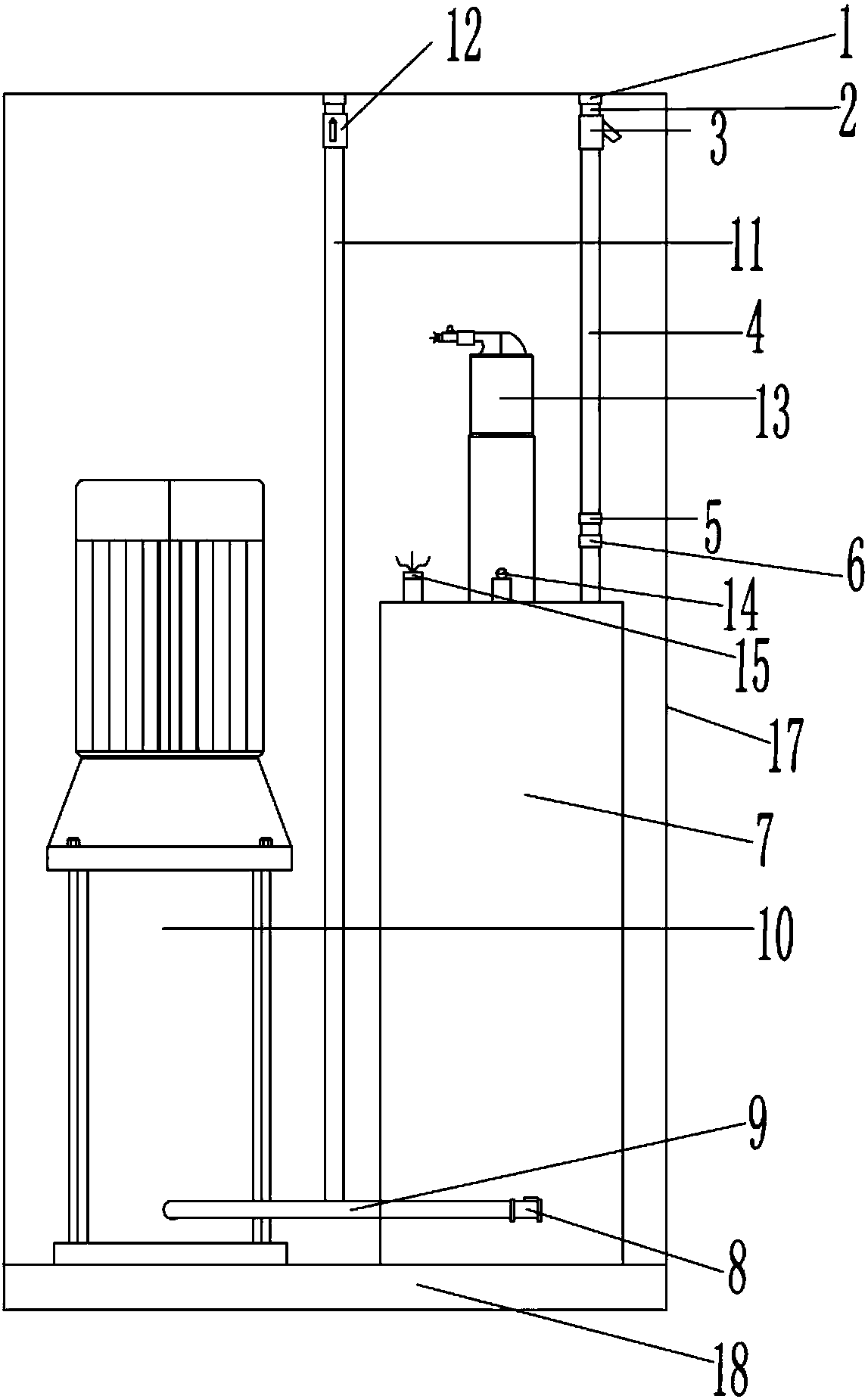
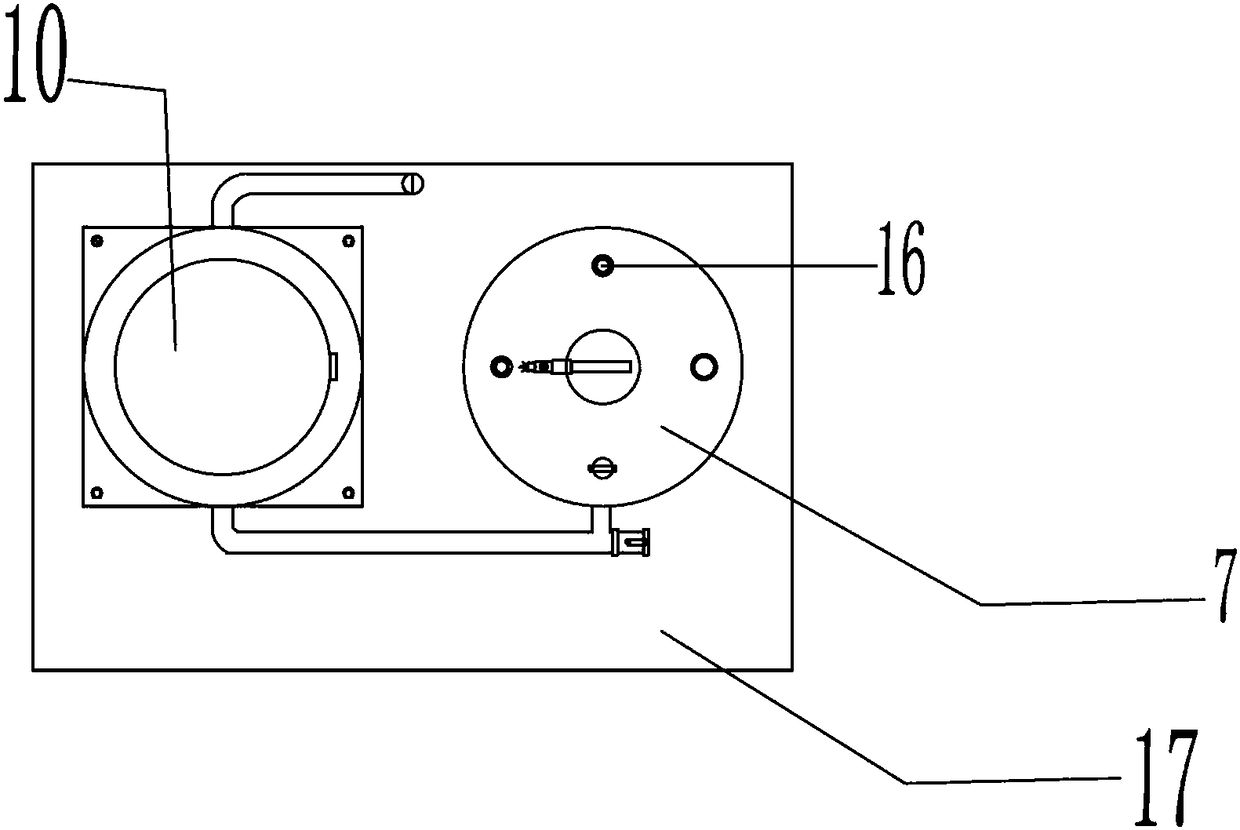
[0053] Such as Figures 1 to 5As shown, an intelligent vacuum degasser includes: a casing 17 and an increasing pump 10 and a degassing tank 7 inside the casing 17 . Both the booster pump 10 and the degassing tank 7 are located on the base 18 .

[0054] The shell 17 forms protection for internal equipment, such as a degassing tank, a booster pump, etc., which is beneficial to prolonging the service life of the equipment.

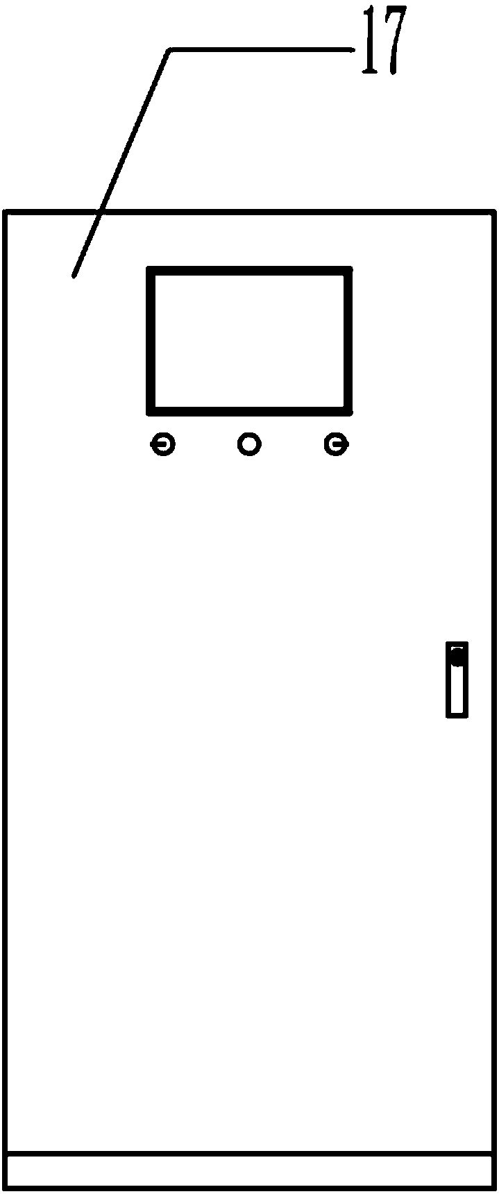
[0055] One side of the casing 17 is provided with a door that can be opened or closed for putting in equipment such as the pump 10 and the degassing tank 7. The inside of the casing 17 is provided with a controller, and the door of the casing 17 is provided with a touch screen , the touch screen is connected to the controller through a signal line. It is convenient to set various parameters through the touch screen.

[0056] The top of the degassing tank 7 is provided with a pressure sensor 15 , a pressure gauge 14 , a real-time online gas monitoring devic...


PUM


Abstract

The invention discloses a control system and a control method of an intelligent vacuum degassing machine, . The control system comprises a controller, degassing tank, a booster tank pump, a water inlet pipeline, a first water outlet pipeline and a second water outlet pipeline; the water inlet of the degassing tank is connected to the water outlet of the water circulation system through the water inlet pipeline; the water outlet of the degassing tank is connected to the booster tank pump through a first outlet pipeline; one end of the second water outlet pipeline is connected to the booster pump; the other end of the second water outlet pipeline is connected to the external water circulation system; the water inlet pipeline is provided with a solenoid valve and a temperature sensor; the intelligent vacuum degassing machine is provided with a real-time online gas monitoring device, a pressure sensor and a liquid level sensor; the solenoid valve, the temperature sensor, the real-time online gas monitoring device, the pressure sensor and the liquid level sensor are electrically connected to the controller; and the controller performs control on the system through the high efficiency automatic control mode and the energy saving automatic control mode. The control system and control method can realize online and intelligent control on the gas, the temperature and the pressure.

Description

technical field [0001] The invention relates to the technical field of degassing, in particular to a control system and a control method of an intelligent vacuum degasser. Background technique [0002] Vacuum degasser is an important equipment used in heating, heat exchange, refrigeration and other water circulation systems. Because there is a large amount of gas in the water circulation system, if it is not removed, the system is prone to air resistance, which will cause poor circulation and uneven heating and cooling of the local or entire system, and cause damage to the equipment and pipelines in the system. At the same time, due to the dissolved oxygen in the water, the terminal equipment such as heating (refrigeration) equipment, pipelines and steel radiators are corroded, perforated, and leaked, which directly affects the safety of the entire system. At the same time, the gas in the system will cause the cavitation of the water pump and the wear of the bearing and gen...

Claims


Application Information

Patent Timeline
Patent Type & Authority Patents(China)
IPC IPC(8): G05D27/02B01D19/00
CPCB01D19/00G05D27/02
Inventor 向文鉴姜涵睿
Owner 北京德安源环境科技发展有限公司
Learn More