Supercharge Your Innovation With Domain-Expert AI Agents!

LED adjustable power switch color temperature modulation control drive circuit

A driving circuit and power switch technology, which is applied in the field of LED adjustable power switch color temperature control driving circuit, can solve problems such as complex structure, achieve the effect of reducing peripheral circuits and saving system costs

Active Publication Date: 2017-09-15
无锡恒芯微科技有限公司
View PDF6 Cites 5 Cited by
  • Summary
  • Abstract
  • Description
  • Claims
  • Application Information

AI Technical Summary

Problems solved by technology

For example, the patent application number 201310057625.7 discloses a LED driver circuit with adjustable light and adjustable color temperature, which is used to drive an LED lighting device composed of N LED light strings, N≥2, including a buck-type power stage circuit, A control and drive circuit and N controllable switches; wherein, each of the LED lamp strings is connected in series with a corresponding controllable switch, and the freewheeling diode in the buck-type power stage circuit is connected to the buck Between the common connection terminal of the power switch tube and the output inductor in the type power stage circuit and a ground potential; the control and drive circuit generates N+1 control signals according to the dimming and color temperature information of the LED lighting device , to respectively control the switching action of the power switch tube and the N controllable switches, which is provided with an MCU separately, and has a complex structure

Method used


Image

  • LED adjustable power switch color temperature modulation control drive circuit
  • LED adjustable power switch color temperature modulation control drive circuit
  • LED adjustable power switch color temperature modulation control drive circuit

Examples


Embodiment Construction

[0014] The specific implementation manners of the present invention will be described in detail below in conjunction with the accompanying drawings.

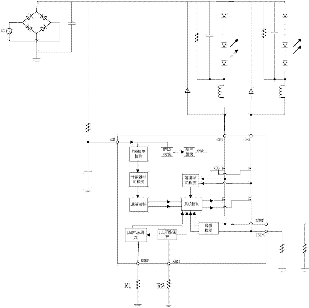
[0015] like figure 1 As shown, the LED adjustable power switch color temperature control drive circuit of the present invention includes a power supply module, two LED lighting circuits and a dimming circuit; the LED lighting circuit includes LED lamp tubes, resistors, capacitors and inductors, LED A capacitor, a resistor and an inductor are connected in parallel at both ends of the lamp tube, and a Schottky tube is arranged between the inductor and the LED lamp. The inductor discharges through the Schottky tube and the LED lamp tube, and this discharge time is the demagnetization time; otherwise, it is the magnetization time.

[0016] The LED dimming circuit includes a channel selection module, a system control module, a demagnetization time detection module, a peak detection module, an LED current setting module, an LED open ...


PUM


Abstract

The invention provides an LED adjustable power switch color temperature modulation control drive circuit which comprises a power supply module, two LED lighting circuits and a dimming circuit. Each LED lighting circuit comprises an LED light tube, a resistor, a capacitor, an inductor, an LED current setting module and an LED open circuit protection module. The LED open circuit protection module comprises an adjusting resistor R2 which is used for setting the minimum demagnetization time of the inductor. The LED current setting module comprises an adjusting resistor R1. The LED current setting module sets the inductor current according to the resistance of the resistor R1 and the adjusting resistor R2. The LED power is adjusted. The entire system only has a control chip. External circuits are reduced. The system cost is saved. Through external resistors, LED current in color mixture is adjusted.

Description

technical field [0001] The invention relates to the technical field of LED driving, in particular to an LED adjustable power switch color temperature control driving circuit. Background technique [0002] At present, most of the LED switch color temperature control systems use 3-chip control, including two LED driver chips and one MCU. For example, the patent application number 201310057625.7 discloses a LED driver circuit with adjustable light and adjustable color temperature, which is used to drive an LED lighting device composed of N LED light strings, N≥2, including a buck-type power stage circuit, A control and drive circuit and N controllable switches; wherein, each of the LED lamp strings is connected in series with a corresponding controllable switch, and the freewheeling diode in the buck-type power stage circuit is connected to the buck Between the common connection terminal of the power switch tube and the output inductor in the type power stage circuit and a gro...

Claims


Application Information

Patent Timeline
Patent Type & Authority Applications(China)
IPC IPC(8): H05B33/08H05B44/00
CPCH05B45/00Y02B20/30
Inventor 吴建良顾南昌吴洁
Owner 无锡恒芯微科技有限公司
Features
  • R&D
  • Intellectual Property
  • Life Sciences
  • Materials
  • Tech Scout
  • Unparalleled Data Quality
  • Higher Quality Content
  • 60% Fewer Hallucinations
Learn More