
A 3D printing layer-by-layer detection reverse part model and device and method for locating defects

A technology of 3D printing and parts, which is applied in the field of 3D printing layer-by-layer detection, reverse part model and defect positioning device, so as to avoid the effect of destructive test

Active Publication Date: 2019-12-10
SOUTH CHINA UNIV OF TECH
View PDF4 Cites 0 Cited by
  • Summary
  • Abstract
  • Description
  • Claims
  • Application Information

AI Technical Summary

Problems solved by technology

Find the cause and propose solutions by analyzing the printing defects of the parts

Method used


Image

  • A 3D printing layer-by-layer detection reverse part model and device and method for locating defects
  • A 3D printing layer-by-layer detection reverse part model and device and method for locating defects
  • A 3D printing layer-by-layer detection reverse part model and device and method for locating defects

Examples


Embodiment

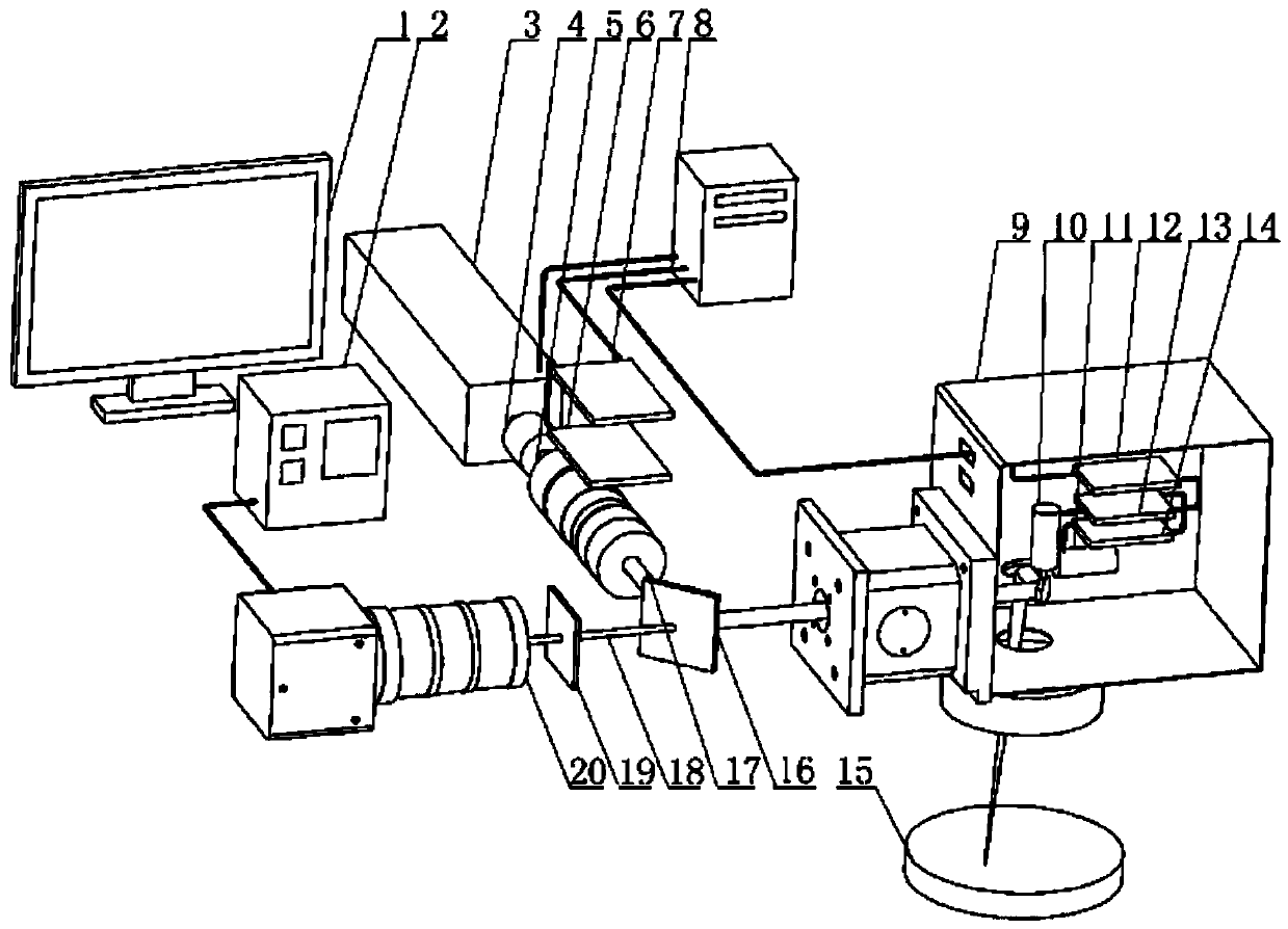
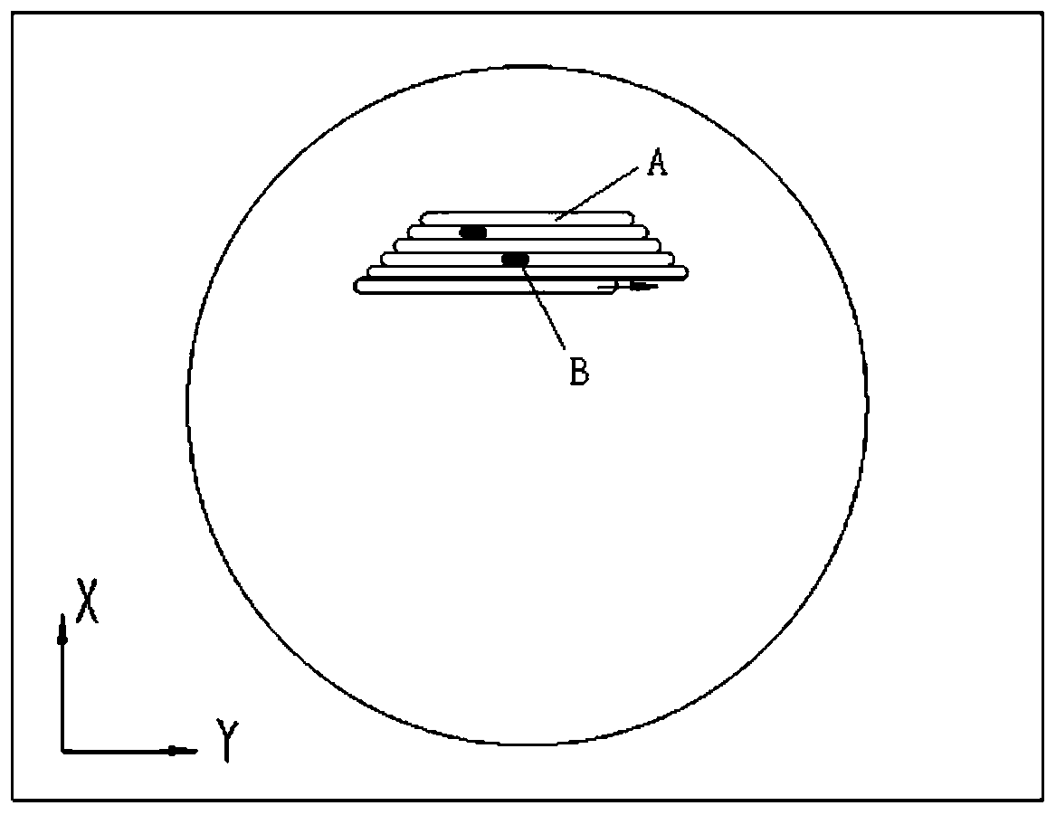
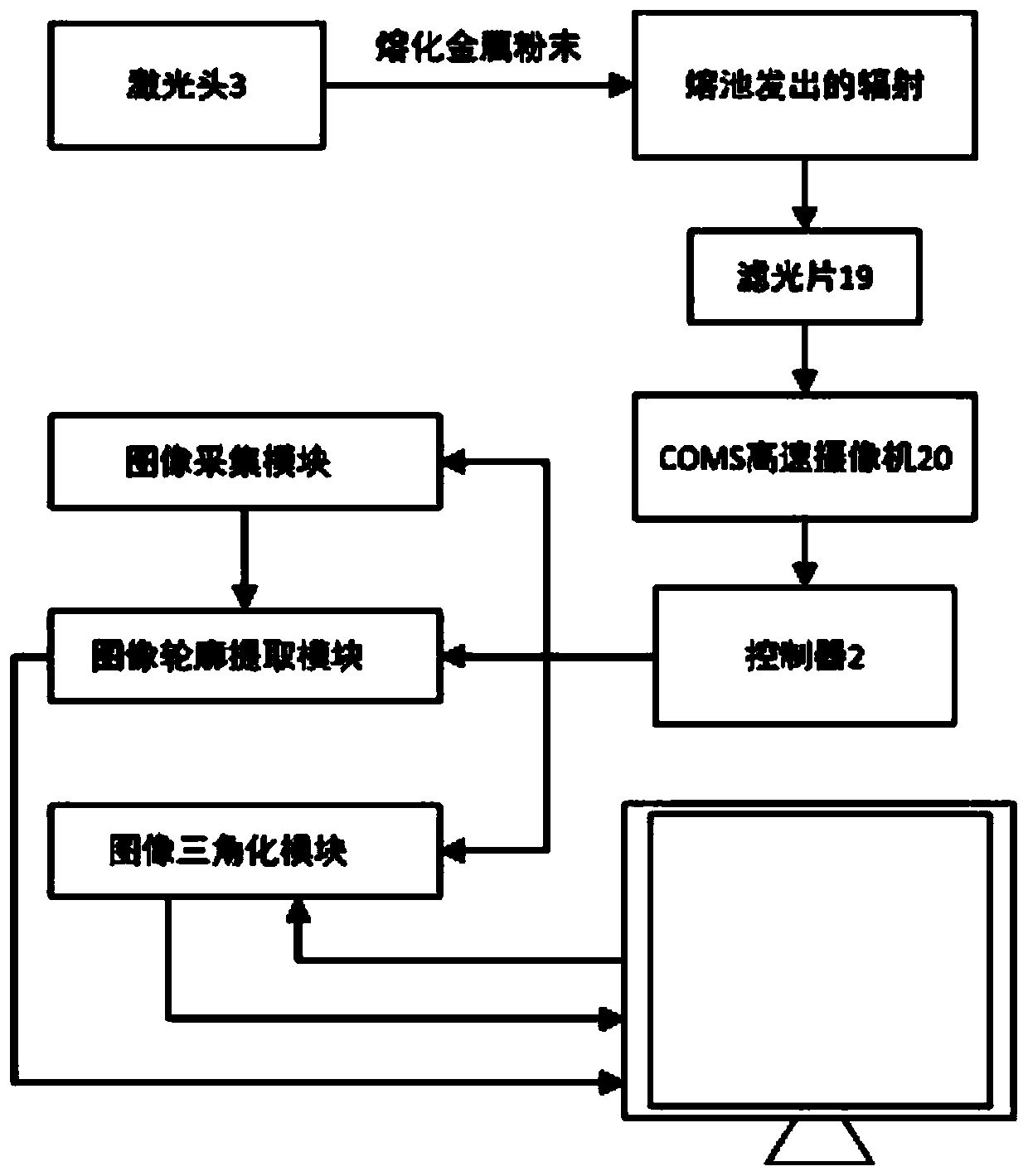
[0032] as the picture shows. The invention discloses a 3D printing layer-by-layer detection and reverse parts model and a device for locating defects, including a laser head 3, a scanning galvanometer 9, a computer 1, a half-transparent mirror 16, a high-speed camera 20, and a controller 2; The high-speed camera 20 is telecommunications connected with the computer 1 through the controller 2;

[0033] The laser light path 17 of the laser head 3 is reflected into the scanning vibrating mirror 9 through the semi-transparent mirror 16, and the laser beam is controlled by the scanning vibrating mirror 9 to selectively melt the metal powder laid on the work platform 15; The mirror 9 collects the molten pool radiation, and transmits it to the high-speed camera 20 through the half-transparent mirror 16, and the high-speed camera 20 processes the molten pool radiation data, and converts the image information into the controller 2, and the controller 2 uses It is used to process the im...


PUM

PropertyMeasurementUnit
wavelengthaaaaaaaaaa

Abstract

The invention discloses a 3D printing layer-by-layer detection and inverse part model and a device and method for positioning defects. The scanning galvanometer is used to control the laser beam to selectively melt the metal powder, and the semi-transparent mirror reflects the molten pool radiation into the high-speed camera and converts it into image information and transmits it to the controller. This device monitors the powder melting in the SLM process, and feeds it back to the computer software interface to reflect the characteristics of the molten pool at different positions in real time, and accurately measure the contour of each molten layer, obtain the part model by inverse method, and compare the model with the The original 3D model is compared and analyzed to obtain the error of the metal 3D printed parts and the original model data in terms of precision and size. The position and three-dimensional shape of internal defects in the 3D printing process can be accurately obtained, avoiding the destructive testing of parts in the later stage of printing parts.

Description

technical field [0001] The invention relates to metal 3D printing process monitoring and precise quality control, in particular to a 3D printing layer-by-layer detection reverse part model and a device and method for locating defects. Background technique [0002] Selective Laser Melting (SLM) technology is a rapid prototyping 3D printing technology that can directly form high-density, high-precision metal parts, but more than 50 different factors are at play in the melting process, such as size and Shape errors, voids in the fused layer, high residual stress in the final part, and the interrelationship of various variables such as material properties make the printing process difficult to quantitatively control. [0003] The development of quality monitoring has led to a significant improvement in the surface roughness and performance of the molded parts in additive manufacturing technology, reducing the deformation of the internal structure. A series of key parameters nee...

Claims


Application Information

Patent Timeline
Patent Type & Authority Patents(China)
IPC IPC(8): B22F3/105G01N21/88B33Y30/00B33Y50/02
CPCG01N21/8851B22F3/003B33Y30/00B33Y50/02G01N2021/8887B22F10/00B22F10/38B22F12/49B22F12/90B22F10/31B22F10/28B22F12/44Y02P10/25
Inventor 王迪王艺锰杨永强
Owner SOUTH CHINA UNIV OF TECH
Learn More