Luminous tube detection method and device thereof

A detection method and detection device technology, applied in measuring devices, optical instrument testing, measuring fluid pressure, etc., can solve problems such as low efficiency and difficulty in realizing full inspection, so as to improve efficiency, reduce product loss, and avoid destructive tests Effect

Inactive Publication Date: 2010-07-28
威力盟电子(苏州)有限公司 +1
View PDF3 Cites 0 Cited by
  • Summary
  • Abstract
  • Description
  • Claims
  • Application Information

AI Technical Summary

Problems solved by technology

[0005] In view of the deficiencies in the above-mentioned background technology, the object of the present invention is to provide a lamp tube detection method and its device to solve the problem of low efficiency and difficulty in achieving full inspection caused by destructive tests on the internal pressure specification detection of lamp tube products. problem

Method used


Image

  • Luminous tube detection method and device thereof
  • Luminous tube detection method and device thereof
  • Luminous tube detection method and device thereof

Examples


Embodiment 1

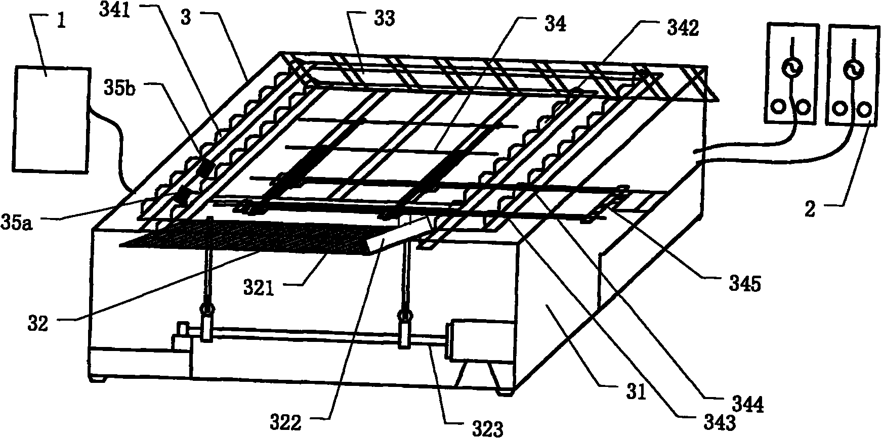
[0059] Such as image 3 Shown is the structural representation of the lamp tube detection device of the present invention, by image 3 It can be seen that the lamp detection device also includes a control unit 1, a power controller 2 and a detection platform 3, and its characteristic design is mainly reflected in that the detection platform 3 has a lamp accommodation groove 33a, a base 31 and a The transfer mechanism 34, wherein:

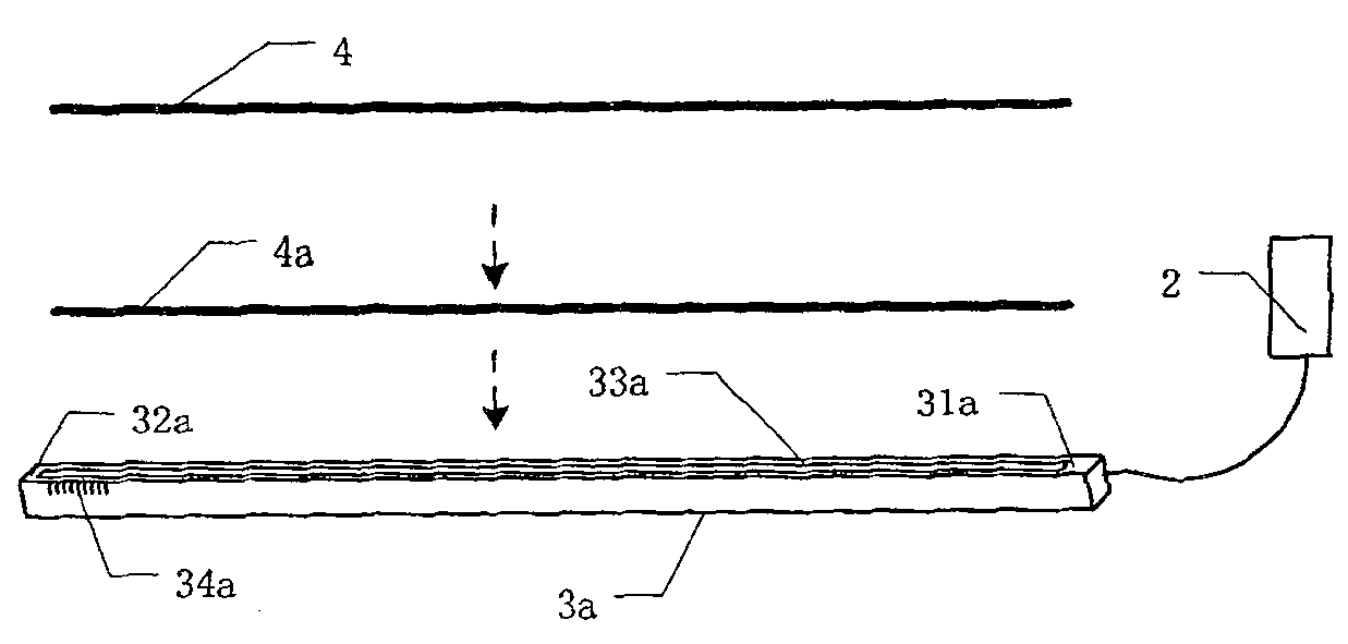
[0060] One end of the lamp accommodating groove 33a is provided with a high-voltage electrode 31a connected to the power controller 2, and the other end is provided with a low-voltage electrode 32a forming a loop.

[0061] A loading area 32 and an unloading area 33 are fixed on both sides of the upper part of the base 31 , and a conveying mechanism 34 is provided between the loading area 32 and the unloading area 33 . The feeding area 32 includes a feeding guide surface 321, a bakelite block 322 and a feeding cam mechanism 323, the bakelite block ...

Embodiment 2

[0068] Such as Figure 4 As shown, it is a schematic diagram of a further optimized structure of the lamp tube detection device of the present invention. Compared image 3 It can be seen that, in order to minimize the influence of external light on the two sensors, based on the derivation of the first embodiment, a light shield 36 is provided on the detection platform 3 . The shade 36 is connected to one side of the base 31 through a hinge 361 . When the detection device is working, the shading cover 36 can be covered, so that the influence of external light on the two sensors on the detection platform 3 can be effectively shielded, and the detection accuracy can be improved. It should be noted that: the shading cover 36 is openable, connected to any side of the square base 31, and the shape of the shading cover 36 can be image 3 The trapezoidal shape shown can also be arc-shaped or other geometric shapes. In addition, the connection between the shading cover 36 and the b...


PUM


Abstract

The invention discloses a lamp tube detection method and a device thereof which are used for detecting the internal voltage of a lamp tube which is internally encapsulated by gas; whether the internal voltage of the lamp tube to be detected exceeds the requirement of the specification or not is judged by the difference of lighting duration of lamp tubes to be detected with different internal voltages and lamp tubes with standard internal voltages under the same driving voltage. The detection method and the device can avoid the damage test for detecting the internal voltage of the cold cathodefluorescent lamp tube, ensure that all lamp tubes can be detected and greatly improve the detection and selection efficiency of the lamp tubes.

Description

technical field [0001] The invention relates to a lamp tube detection method and its device, in particular to a lamp tube inner pressure detection method and device thereof sealed with gas. Background technique [0002] Cold Cathode Fluorescent Lamp (CCFL, Cold Cathode Fluorescent Lamp), its light emitting principle is the same as that of ordinary fluorescent lamps. Mercury and rare gas are contained inside the fluorescent tube, and the rare gas used in high-efficiency cold cathode fluorescent tubes is mainly a mixed gas of neon (Ne) and argon (Ar). When the lamp tube applies voltage to both ends of the electrodes, electrons can be released at the tip of the electrodes, and these released electrons will collide with the internal mercury and excite the mercury atoms to produce a stable state-unstable state-stable state rapid transition, which consumes The energy is released in the form of ultraviolet rays (wavelengths of 253.7nm and 185nm). The inner wall of the cold cathod...

Claims


Application Information

Patent Timeline
Patent Type & Authority Patents(China)
IPC IPC(8): G01L11/00G01M11/00
Inventor 杨宗宪孙红卫刘远辉张盛强
Owner 威力盟电子(苏州)有限公司
Why Eureka
Try Eureka