Unmanned aerial vehicle hangar

A technology for hangars and drones, applied in motor vehicles, aircraft parts, buildings where cars are parked, etc., can solve the problems of low charging efficiency and high cost of charging equipment, to ensure safety, improve land use efficiency, ensure Effects of stability and security

Inactive Publication Date: 2017-09-19
SKYSYS INTELLIGENT TECH SUZHOU CO LTD
View PDF1 Cites 48 Cited by
  • Summary
  • Abstract
  • Description
  • Claims
  • Application Information

AI Technical Summary

Problems solved by technology

[0005] By setting up UAV charging hangars in a distributed manner, the endurance of UAVs can be effectively extended, but it is wireless charging. Compared with wired charging, not only the charging efficiency is low, but the cost of charging equipment is high

Method used


Image

  • Unmanned aerial vehicle hangar
  • Unmanned aerial vehicle hangar
  • Unmanned aerial vehicle hangar

Examples


Embodiment 1

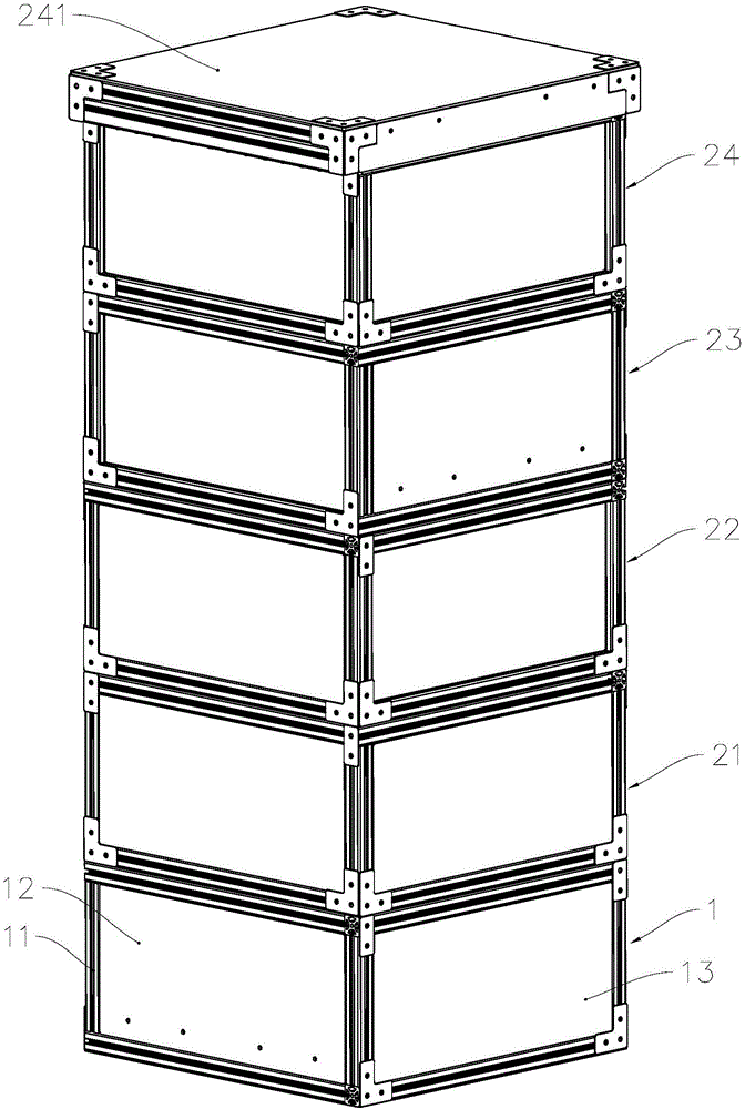
[0031] see figure 1 , from bottom to top, the UAV hangar includes a controller, a library unit 1, a library unit 21, a library unit 22, a library unit 23 and a top library unit 24, and the adjacent two layers of library units are detachably fixed by fixing pieces In actual use, different layers of library units can be configured according to the number of drones that need to be docked.

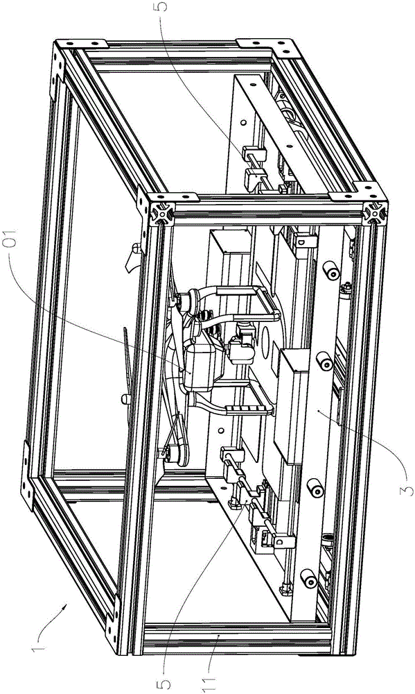
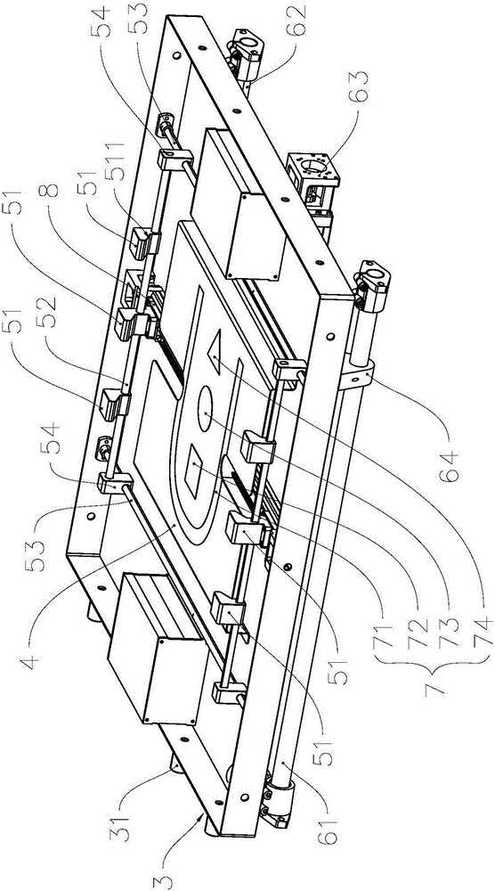
[0032] see Figure 1 to Figure 4, taking the library unit 1 at the bottom as an example to illustrate the structure of the library unit, which includes a support frame 11, a protective case and a push-pull drawer structure installed in the protective case. The push-pull drawer structure includes a push-pull plate 3, an apron 4, A pair of clamping components 5 and a push-pull actuator 63 that drives the push-pull plate 3 to slide along the guide rods 61 and 62 .

[0033] Both the apron 4 and the pressing assembly 5 are installed on the push-pull plate 3 to be pushed out or pulled into the pro...

Embodiment 2

[0070] As a description of Embodiment 2 of the present invention, only the differences from Embodiment 1 above will be described below.

[0071] see Figure 5 to Figure 8 , the apron 4 is a hollow plate structure, which is supported by a plurality of support plates between it and the push-pull plate 32, forming an overhead layer structure with ventilation on both sides; the two side plates 33 of the drawer structure are all provided with through holes and are used in night environments. The LED light strip 35 for the lower lighting, the front panel 34 and the push-pull plate 32 are hinged through a hinge, and the actuator 36 is used to push the front panel 34 to rotate around the hinge axis to control the front panel 34 to switch between the tiled position and the erect position. By setting through holes on the apron 4 and the side plate 33, and making the front panel 34 in a flat state during the take-off and landing of the drone, the rebound to the downwash airflow of the ro...

Embodiment 3

[0086] As an explanation of Embodiment 3 of the present invention, only the differences from Embodiment 1 above will be described below.


PUM


Abstract

The invention relates to an unmanned aerial vehicle hangar, and belongs to the technical field of landing assistance of unmanned aerial vehicle. The unmanned aerial vehicle hangar comprises a controller, a parking apron and an automatic charging device, wherein the automatic charging device is controlled by the controller. The controller comprises a memory and a processor; the automatic charging device comprises a pair of clamping and pressing assemblies; each clamping and pressing assembly comprises a clamping claw, an actuator and a charging electrode, wherein the clamping claw is used for clamping and pressing a landing gear transverse rod of the unmanned aerial vehicle; the clamping claw is driven by the actuator to move in the position between clamping and pressing charging position and releasing position, and the charging electrode is fixedly arranged on the charging claw. By arranging the clamping claw and fixedly arranging the charging electrode on the clamping claw, the unmanned aerial vehicle under the charging state is fixed to the parking apron, so that continuity and stability of the charging process are guaranteed.

Description

technical field [0001] The invention relates to an auxiliary device for landing an unmanned aerial vehicle, in particular to a hangar for an unmanned aerial vehicle with an automatic charging device. Background technique [0002] Unmanned aircraft, that is, UAV, is an unmanned aircraft operated by radio remote control equipment and its own program control device. It has low cost, good cost-effectiveness, low risk, strong survivability, and good maneuverability advantages, and is widely used in high-altitude shooting, and has a strong application prospect in the field of express delivery. [0003] UAVs are usually powered by batteries mounted on them, limited by the limited weight of the batteries that can be carried, and the power consumption increases with the increase of auxiliary equipment, resulting in a short single voyage, which limits its application prospects and develop. [0004] In order to prolong the battery life of the UAV, a patent document with the publicati...

Claims


Application Information

Patent Timeline
Patent Type & Authority Applications(China)
IPC IPC(8): B60L11/18E04H6/44
CPCB60L53/11B60L53/14B60L53/16B60L53/36B60L53/37B60L53/51B60L2200/10B64F1/007B64F1/125E04H6/44Y02T10/70Y02T10/7072Y02T90/12Y02T90/14
Inventor 王海滨钱茂冬胡天波周浩高杰徐乐胡益汀
Owner SKYSYS INTELLIGENT TECH SUZHOU CO LTD
Why Eureka
Try Eureka