Quenching device for vane pump rotors

A technology of quenching device and vane pump, which is applied in the direction of quenching device, furnace type, heat treatment equipment, etc., can solve the problems of timing opening of the discharge switch, trouble and other problems, and achieve the effect of reducing waste

Active Publication Date: 2017-09-19
长春市第一水泵有限公司
View PDF3 Cites 6 Cited by
  • Summary
  • Abstract
  • Description
  • Claims
  • Application Information

AI Technical Summary

Problems solved by technology

But there are still the following defects: 1. It is very troublesome to turn on the discharge switch regularly after the heat treatment of the parts
2. It is necessary to artificially supplement the feed all the time

Method used


Image

  • Quenching device for vane pump rotors

Examples


Embodiment Construction

[0022] The present invention will be described in further detail below by means of specific embodiments:

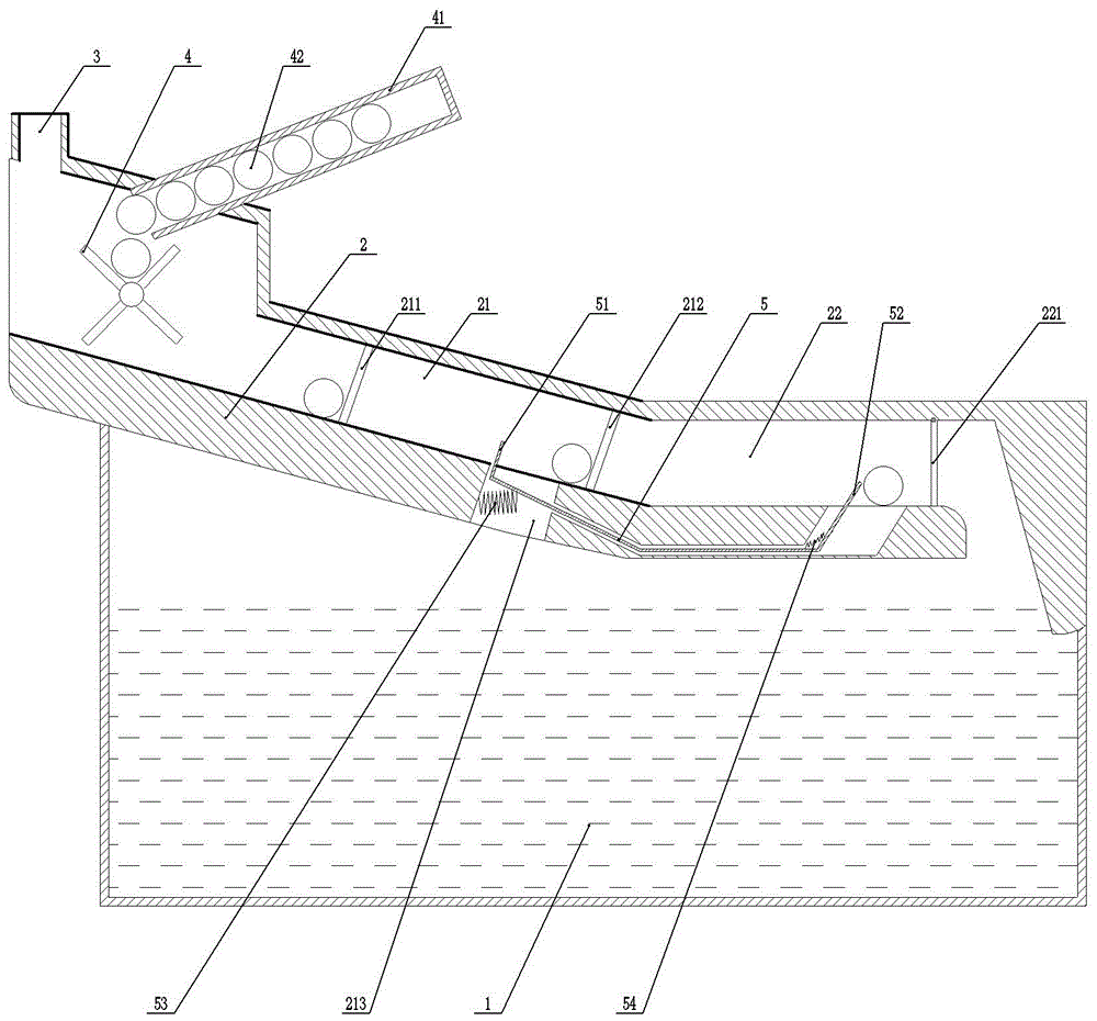
[0023] The reference signs in the drawings of the description include: quenching oil pool 1, furnace body 2, chute section 21, first material door 211, second material door 212, through hole 213, flat section 22, third material door 221, Smoke outlet 3, flip feeding rack 4, feed section 41, vane pump rotor 42, slide plate 5, push plate 51, drive plate 52, extension spring 53, spring 54.

[0024] Such as figure 1 As shown, the vane pump rotor quenching device includes a feeding unit, a quenching oil pool 1, a smoke exhaust unit and a furnace body 2. The outer surface of the furnace body 2 is covered with a heat insulation layer. The setting of the heat insulation layer can effectively prevent the furnace body from 2. The heat inside is dissipated to the outside, reducing energy loss. The body of furnace 2 comprises the chute section 21 and the flat section 22 which are i...


PUM

PropertyMeasurementUnit
thicknessaaaaaaaaaa

Abstract

The invention belongs to the technical field of heat treatment equipment, and particularly discloses a quenching device for vane pump rotors. The quenching device comprises a feeding unit, a furnace body and quenching oil pool, and the furnace body comprises a chute section and a flat section; a first material door and a second material door are arranged in the chute section, and a third material door is hinged to the upper portion of one side of the flat section; a slide groove is formed in the bottom of the furnace body, the gradient of the part, located at the chute section, of the slide groove is greater than the gradient of the chute section; a through hole is formed in the chute section, a flexible slide plate is connected in the slide groove in a sliding mode, and a tension spring is connected on the side wall of the through hole; a driving plate is fixed to one end of the slide plate, a push plate is hinged to the other end of the slide plate, and a spring is connected between the push plate and the slide plate; and the feeding unit comprises a feeding section and an overturning conveying frame, the overturning conveying frame comprises a rotary shaft and overturning plates, and the rotary shaft is connected on the furnace body in a rotating mode. According to the quenching device for the vane pump rotors, automatic supplementary feeding can be achieved, after the vane pump rotors are heated sufficiently, the later-added vane pump rotors can drive the earlier-added vane pump rotors to roll, and thus additionally provided power is not needed.

Description

technical field [0001] The invention belongs to the technical field of heat treatment equipment, in particular to a vane pump rotor quenching device. Background technique [0002] The vane pump is a pump in which the vanes in the rotor groove are in contact with the pump casing, and the sucked liquid is pressed from the oil inlet side to the oil discharge side. The pump is composed of components such as rotor, stator, vane, oil distribution plate and end cover. Before finishing the rotor of the vane pump, heat treatment such as quenching is required for the rotor. Quenching is to heat the product to a certain temperature, preheat it for a period of time, and then heat it above the critical temperature and keep it warm for a period of time to make all or part of the product austenitic. It is a heat treatment process in which martensite (or bainite) transformation is carried out by rapid cooling to below Ms (or isothermal near Ms) at a cooling rate greater than the critical c...

Claims


Application Information

Patent Timeline
Patent Type & Authority Applications(China)
IPC IPC(8): C21D1/63C21D9/00
CPCC21D1/63C21D9/0068
Inventor 王文革
Owner 长春市第一水泵有限公司
Why Eureka
Try Eureka