Rotary vane pump/motor

A technology of rotary vane pumps and vanes, which is applied in the direction of rotary piston pumps, rotary piston machines, pumps, etc., and can solve problems such as low overall energy efficiency, large fluid energy loss, and tortuous road strength

Inactive Publication Date: 2017-09-19
吴其兵
View PDF5 Cites 4 Cited by
  • Summary
  • Abstract
  • Description
  • Claims
  • Application Information

AI Technical Summary

Problems solved by technology

[0002] There are many types of existing pumps/motors, and the common problem is that the path of the fluid in ...

Method used


Image

  • Rotary vane pump/motor
  • Rotary vane pump/motor
  • Rotary vane pump/motor

Examples


Embodiment Construction

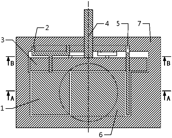
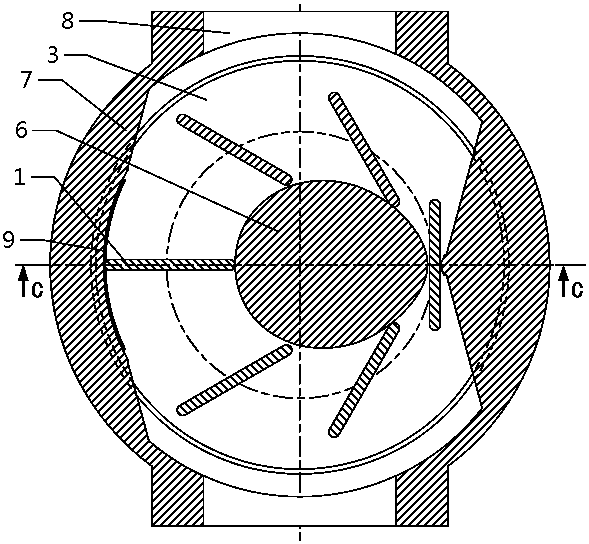
[0028] like figure 2 , image 3 , Figure 4 As shown, this embodiment provides a pump / motor with 6 uniformly distributed blades, including 6 blades 1, 6 synchronous claws 2, runner 3, power shaft 4, synchronous chute 5, shroud 6, Housing 7 and 2 fluid inlet and outlet ports 8 .

[0029] The blade 1 is movably connected with the runner 3, and the blade 1 can rotate relative to the runner 3; the top of each blade 1 is fixedly connected with the synchronous pawl 2, and the protrusion of the synchronous pawl 2 The slide bar is embedded in the groove of the synchronous chute 5; the runner 3 is fixedly connected with the power shaft 4; when the blade 1 is driven by fluid (motor working condition) or the runner 3 is driven by the When the power shaft 4 is driven (pump working condition), the blade 1 revolves with the runner 3, and at the same time, the protruding sliding rod of the synchronous pawl 2 connected to the blade 1 moves along the groove of the synchronous chute 5. The...


PUM


Abstract

The invention provides a rotary vane pump/motor with simple structure, which includes vanes, synchronous claws, runners, power shafts, synchronous chute, shroud, casing and inlet and outlet ports. A plurality of self-rotating blades are installed on the runner connected to the power shaft, and the ratio of the rotation speed of the blades to the speed of the runner is 1:2. The invention is applicable to various fluids, the working conditions are reversible, the fluid flow direction is reversible, the structure is simple, and the energy efficiency is high. Through the difference design of the blade and the guide structure, it can be used as the design prototype of the water pump, the water turbine, the air pump/motor, and the hydraulic pump/motor respectively. .

Description

technical field [0001] The present invention relates to a rotary vane pump / motor. Background technique [0002] There are many kinds of pumps / motors in existence, but the common problem is that the path of the fluid in the pump / motor is tortuous, resulting in a large loss of fluid energy, and the overall energy efficiency is not high. Contents of the invention [0003] The purpose of the present invention is to overcome the shortcomings of the above-mentioned tortuous fluid path, and to invent a pump / motor with a direct fluid path. [0004] The technical scheme adopted in the present invention is: [0005] A number of self-rotating blades are installed on a runner, and the ratio of the rotation speed of the blades to the rotation speed of the runner is 1:2, that is, every time the runner rotates 360 degrees, the blades rotate 180 degrees; therefore, in In the entire 360-degree interval, there is a section where the direction of motion of the blade is nearly perpendicular...

Claims


Application Information

Patent Timeline
IPC IPC(8): F04C2/44
CPCF04C2/44
Inventor 吴其兵
Owner 吴其兵
Why Eureka
Try Eureka