
Backlight module and display device

A backlight module and light source technology, applied in lighting devices, lighting device parts, optics, etc., can solve the problem of the warped state of the diffuser sheet.

Active Publication Date: 2017-09-19
WUHAN CHINA STAR OPTOELECTRONICS TECH CO LTD
View PDF6 Cites 1 Cited by
  • Summary
  • Abstract
  • Description
  • Claims
  • Application Information

AI Technical Summary

Problems solved by technology

[0004] The embodiment of the present invention provides a backlight module and a display device to solve the problem that the diffusion sheet is prone to warping after RA verification

Method used


Image

  • Backlight module and display device
  • Backlight module and display device
  • Backlight module and display device

Examples


Embodiment Construction

[0034] The following descriptions of the various embodiments refer to the accompanying drawings to illustrate specific embodiments in which the present invention can be practiced. The directional terms mentioned in the present invention, such as "up", "down", "front", "back", "left", "right", "inside", "outside", "side", etc., are for reference only The orientation of the attached schema. Therefore, the directional terms used are used to illustrate and understand the present invention, but not to limit the present invention.

[0035] exist Figure 1 to Figure 5 In , structurally similar units are denoted by the same reference numerals.

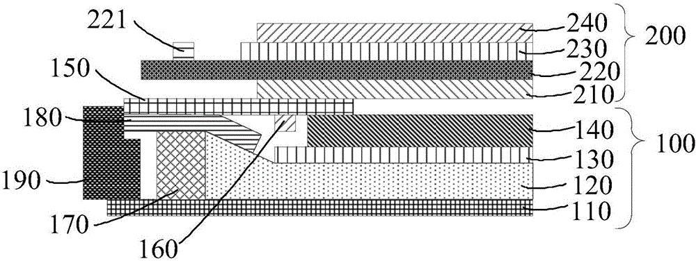
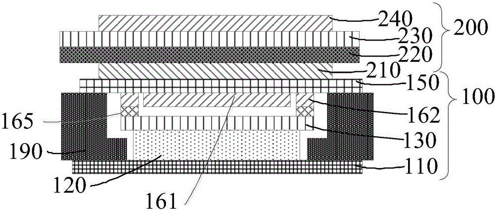
[0036] See figure 1 with figure 2 as shown, figure 1 It is a schematic structural diagram of a display device in an embodiment of the present invention; figure 2 It is a schematic cross-sectional structure diagram of a display device in an embodiment of the present invention.

[0037] The display device provided by this embodiment inc...


PUM


Abstract

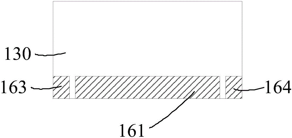
The invention provides a backlight module and a display device. The backlight module comprises a light guide plate comprising the light entering surface, the light emitting surface and the reflecting surface, a reflector, a diffuser, a prismatic lens set, a rim tape, a light source and a light shield layer, wherein the reflector is arranged on the reflecting surface of the light guide plate, the diffuser is arranged on the light emitting surface of the light guide plate, the prismatic lens set is arranged on the light emitting surface of the diffuser, the rim tape is arranged around the light emitting surface of the light guide plate, the light source is arranged on one side of the light entering surface of the light guide plate, and the light shield layer is arranged between the diffuser and the rim tape and arranged on the outer side of the prismatic lens set in the mode that the light shield layer corresponds to the side of incident light of the diffuser. The light shield layer comprises a middle section and side sections which are separated, and the length of the middle section is larger than the length of each side section. The two sides of the side sections are fixedly connected with the diffuser and the rim tape correspondingly, and only one side of the middle section is fixedly connected with the rim tape. Under the condition of high temperatures or low temperatures or the like, the light shield layer and the diffuser move relatively, and warping of the light shield layer and the diffuser is avoided.

Description

technical field [0001] The invention relates to the field of display technology, in particular to a backlight module and a display device. Background technique [0002] At present, mobile phone modules are becoming thinner and thinner. Diaphragm warping (Waving) after RA verification (reliability testing in harsh environments such as high temperature and high humidity after product molding) has become a concern The problem, this is often related to whether the module can be mass-produced. [0003] Most of the warping is related to the diffuser, and the diffuser is prone to warping after RA verification. Contents of the invention [0004] Embodiments of the present invention provide a backlight module and a display device to solve the problem that the diffusion sheet RA is prone to warping after verification. [0005] An embodiment of the present invention provides a backlight module, including: [0006] A light guide plate, including a light incident surface, a light ex...

Claims


Application Information

Patent Timeline
IPC IPC(8): F21K9/20F21V7/00F21V5/02F21V23/00H04M1/22F21Y115/10
CPCH04M1/22F21K9/20F21V5/02F21V7/00F21V23/003F21Y2115/10G02F1/133615G02F2201/54G02B6/0055G02B6/0051G02B6/0053G02B6/009G02B6/0095G02B6/0066F21K9/00
Inventor 徐鹏博
Owner WUHAN CHINA STAR OPTOELECTRONICS TECH CO LTD
Learn More