Micro-strip combiner and installation structure thereof

An installation structure and combiner technology, applied in the direction of circuits, waveguide devices, electrical components, etc., can solve the problems of bulky, high cost, narrow bandwidth, etc., achieve good intermodulation stability, prevent radiation interference, and reduce costs Effect

Inactive Publication Date: 2017-09-19
GUANGDONG SHENGLU TELECOMM TECH
View PDF7 Cites 2 Cited by
  • Summary
  • Abstract
  • Description
  • Claims
  • Application Information

AI Technical Summary

Problems solved by technology

At present, there are two types of dual frequency combiners on the market: cavity and microstrip board. Although the cavity combiner with better optimization results has stable performance and extremely small insertion loss, the materials used are all metal, and Bulky and expensive
The biggest advantage of the microstrip board is that it is small in size, light in weight, and very low in cost, but the disadvantage is that the bandwidth is narrow, and due to technical limitations, most of the occasions cannot meet the requirements.

Method used


Image

  • Micro-strip combiner and installation structure thereof
  • Micro-strip combiner and installation structure thereof
  • Micro-strip combiner and installation structure thereof

Examples


Embodiment Construction

[0018] The technical solution will be described in detail below in conjunction with specific embodiments.

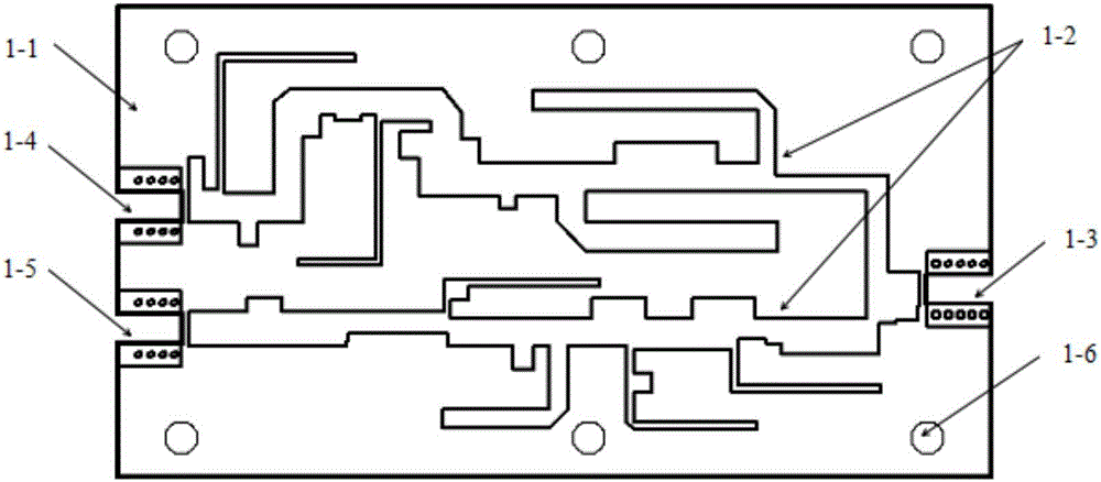
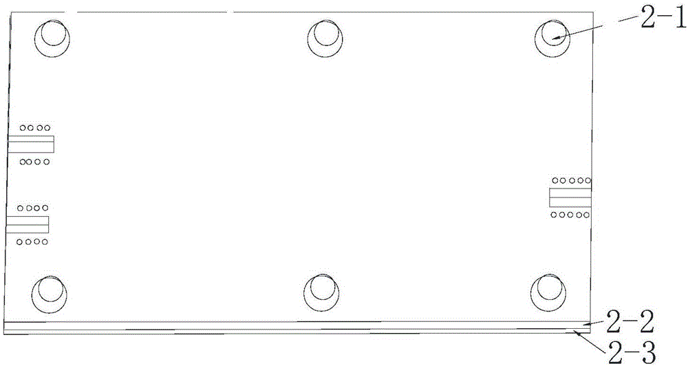
[0019] like Figure 1-Figure 2 Shown, the present invention is a kind of microstrip combiner, and it comprises that the frequency band that is set on the microstrip board is the high-frequency branch of 2300MHz-2690MHz and the frequency band is the low-frequency branch of 1710MHz-2170MHz, and the high-low frequency branch is synthesized into one combined output port. In this embodiment, the high-frequency branch and the low-frequency branch are formed on the front of the microstrip board with a certain thickness according to the simulation results; there are a certain number of fixed holes in the non-trace area. The high-frequency branch is provided with a high-frequency interface, and the low-frequency branch is provided with a low-frequency interface. The high-frequency interface, low-frequency interface and combined output port are all connected to the outside in the...


PUM


Abstract

The present invention discloses a micro-strip combiner. The micro-strip combiner comprises a high-frequency branch having a frequency range of 2300MHz-2690MHz and a low-frequency branch having a frequency range of 1710MHz-2170MHz which are arranged on a micro-strip board, and the high-frequency branch and the low-frequency branch combine one combiner output port. The cost is reduced while the electrical indexes are ensured, a certain technology difficulty is broke through, and the fine optimization is performed at the aspects of dimension control and installation technology. Besides, a connection port is a welding form, and compared to an N-type screw thread interface used by a general cavity combiner, the micro-strip combiner and the installation structure thereof are better in intermodulation stability.

Description

technical field [0001] The invention relates to the technical field of antenna equipment, in particular to a microstrip combiner inside a dual-frequency or multi-frequency antenna. Background technique [0002] With the rapid development of the integration of communication systems, the requirements for the size of the antenna are getting smaller and smaller, and more and more frequency bands are integrated. Signals of different frequency bands generally require independent interfaces, but due to equipment, technology and demand reasons, sometimes the signals of two frequency bands must be combined for input or output, which requires a dual-frequency combiner to achieve. At present, there are two types of dual frequency combiners on the market: cavity and microstrip board. Although the cavity combiner with better optimization results has stable performance and extremely small insertion loss, the materials used are all metal, and The volume is bulky and the cost is high. The...

Claims


Application Information

Patent Timeline
Patent Type & Authority Applications(China)
IPC IPC(8): H01P1/00H01P1/213
CPCH01P1/00H01P1/213
Inventor 丁磊董剑磊宋校曲方雄波贺沙赵国灵
Owner GUANGDONG SHENGLU TELECOMM TECH
Why Eureka
Try Eureka