
Insecticidal lamp assembly

An insecticidal lamp and component technology, which is applied to devices, chemical instruments and methods for catching or killing insects, animal husbandry, etc., can solve the problems of adverse effects of insecticidal lamp components, pest adhesion and other problems, and achieves good application promotion and Use value, reduction of pesticide spraying, effect of food security and soil environmental protection

Inactive Publication Date: 2017-09-22
HUNAN FENGMAO PLANT PROTECTION MACHINERY CO LTD
View PDF2 Cites 13 Cited by
  • Summary
  • Abstract
  • Description
  • Claims
  • Application Information

AI Technical Summary

Problems solved by technology

[0005] The first object of the present invention is to provide an insecticidal lamp assembly to solve the problem that after the pests are killed by the insecticidal lamp assembly in the prior art, a large number of pest remains adhere to the high-voltage power grid continuously, causing serious problems for insecticides. Technical issues that adversely affect lamp assemblies

Method used


Image

  • Insecticidal lamp assembly
  • Insecticidal lamp assembly
  • Insecticidal lamp assembly

Examples


Embodiment 1

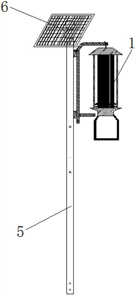
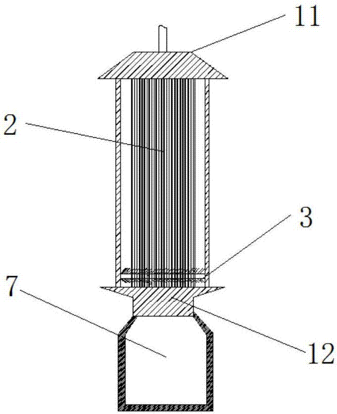
[0035] The first embodiment is an insecticidal lamp assembly, refer to figure 1 and figure 2 As shown, it includes an insecticidal lamp 1 and a cleaning device for cleaning pests (stunned or killed by a high-voltage power grid 2); the insecticidal lamp 1 includes a high-voltage power grid 2; the cleaning device includes a cleaning brush 3 and a driving cleaning brush 3 A driving element that reciprocates along the outer peripheral side of the high-voltage grid 2 .

[0036] Wherein, the structural form of cleaning device can have many kinds.

[0037] The first type: the cleaning brush 3 moves up and down along the outer peripheral side of the high-voltage power grid 2 to clean up the pests driven by the drive element. At this time, the driving element is any one of a motor, an air cylinder or a hydraulic cylinder.

[0038] The second type: the cleaning brush 3 rotates reciprocally along the outer peripheral side of the high-voltage power grid 2 under the drive of the drivin...

Embodiment 2

[0069] The second embodiment is also a kind of insecticidal lamp assembly, refer to Figure 7 As shown, it includes an insecticidal lamp 1, a horizontal support rod 8 and a cleaning device for cleaning pests; the insecticidal lamp 1 includes a high-voltage power grid 2; the cleaning device includes a cleaning brush 3 and drives the cleaning brush 3 to reciprocate along the outer peripheral side of the high-voltage power grid 2 The drive element of motion; Compared with the existing insecticidal lamp, a cleaning device is added on the insecticidal lamp assembly. Wherein, the cleaning device includes a cleaning brush 3 and a driving element that drives the cleaning brush 3 to reciprocate along the outer peripheral side of the high-voltage power grid 2. Since the pests stunned or killed by the insecticidal lamp 1 will attach to the high-voltage power grid 2, the cleaning The brush 3 moves back and forth on the high-voltage power grid 2 to clean up the remains of pests attached t...


PUM


Abstract

The invention provides an insecticidal lamp assembly, and relates to the technical field of agriculture green prevention and control, the lamp assembly comprises an insecticidal lamp and a cleaning device for cleaning insect pests; the insecticidal lamp comprises high-voltage grid; the cleaning device comprises a cleaning brush and drive components for driving the cleaning brush to make reciprocating movements along the peripheral side of the high-voltage grid; the technical problems that in the prior art adverse effects are made on the insecticidal lamp assembly by the remains of the large number of insect pests constantly glued on the high-voltage grid after the insect pests are killed by the insecticidal lamp are solved; the insecticidal lamp assembly has the technical effects that the insecticidal lamp assembly can be kept clean and are relatively long in service life.

Description

technical field [0001] The invention relates to the technical field of agricultural green prevention and control, in particular to an insecticidal lamp assembly. Background technique [0002] With people yearning for a green life, the country pays more and more attention to health and environmental protection, and high-tech insecticide methods will become people's first choice. [0003] As a kind of pest control electronic equipment, the insecticidal lamp component is a new type of physical insecticidal tool that is worth promoting. The light it emits can trap and kill various pests in the farmland, thereby reducing the use of pesticides, reducing agricultural products, and soil. , water pollution and the purpose of saving farmers' planting costs. [0004] The working principle of the existing insecticidal lamp assembly is mainly to convert low-voltage electricity into high-voltage electricity by using frequency vibration circuits and electronic controllers, and use the pho...

Claims


Application Information

Patent Timeline
Patent Type & Authority Applications(China)
IPC IPC(8): A01M1/04A01M1/22B08B1/00
CPCA01M1/04A01M1/223B08B1/30B08B1/12
Inventor 唐杰唐汇欣
Owner HUNAN FENGMAO PLANT PROTECTION MACHINERY CO LTD
Learn More