Double-punch upsetting machine

A technology of upsetting machines and double punches, which is applied in the direction of upsetting presses, forging presses, forging presses, etc., can solve the problems of high operating costs, labor and space, and achieve operating cost savings, equipment costs, and land occupation Effect of area saving

Active Publication Date: 2017-09-22
CHINA NAT HEAVY MACHINERY RES INSTCO
View PDF5 Cites 11 Cited by
  • Summary
  • Abstract
  • Description
  • Claims
  • Application Information

AI Technical Summary

Problems solved by technology

[0002] The pipe end upsetting machine with a single punch is relatively common. To complete two upsettings in a row, two upsetting machines must be equipped, which requires labor and space and high operating costs.

Method used


Image

  • Double-punch upsetting machine
  • Double-punch upsetting machine
  • Double-punch upsetting machine

Examples


Embodiment Construction

[0014] The present invention will be described in detail below in conjunction with the accompanying drawings.

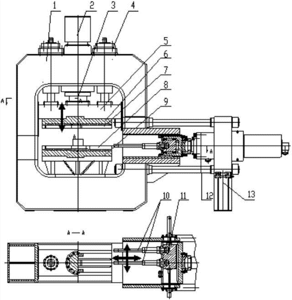
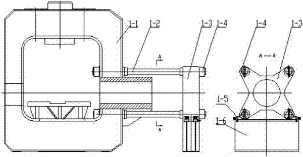
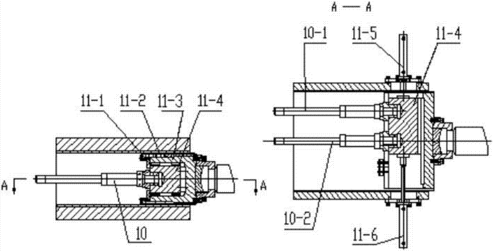
[0015] refer to figure 1 , a double-punch upsetting machine, including a frame 1, a liquid-filled oil tank 2 is installed on the upper part of the frame 1, and the liquid-filled oil tank 2 communicates with a master cylinder 3 fixed on the frame 1 to quickly charge the master cylinder 3. The role of liquid and liquid discharge, the main cylinder 3 piston rod is connected with the moving beam 5, the moving beam 5 is connected with the return cylinder 4 fixed on the frame 1, the main cylinder 3 and the return cylinder 4 drive the moving beam 5 to move up and down, and the moving beam 5. The lower part is connected with an upper die base 6, and an upper die base 7 is installed on the upper die base 6; the lower die base 8 matched with the upper die base 7 is installed on the lower die base 9, and the lower die base 9 is connected with the frame workbench ;

[0016] Th...


PUM


Abstract

The invention discloses a double-punch upsetting machine which comprises a rack. A charging oil tank is installed at the upper portion of the rack. The charging oil tank communicates with a main cylinder fixed to the rack. A piston rod of the main cylinder is connected with a movable beam. The movable beam is connected with a return cylinder fixed to the rack. The lower portion of the movable beam is connected with an upper die seat, and an upper female die is installed on the upper die seat. A lower female die matched with the upper female die is installed on a lower die seat. The lower die seat is connected with a rack worktable. A punch lateral-moving device is connected to the position, on the side of the rack worktable, on the rack. Two punches installed on the punch lateral-moving device are matched with the rack worktable. The punch lateral-moving device is connected with a piston rod of an upsetting cylinder. The first pass of punch and the second pass of punch can be alternately pushed into a work station through the punch lateral-moving device, and two passes of upsetting can be completed. The double-punch upsetting machine is equivalent to two single-punch upsetting machines, and the equipment cost, the occupied area and the running cost are saved nearly by a half.

Description

technical field [0001] The invention relates to an upsetting machine, in particular to a double-punch upsetting machine. Background technique [0002] The pipe end upsetting machine with a single punch is relatively common. To complete two upsettings in a row, two upsetting machines must be equipped, which takes a lot of labor and space, and the operating cost is high. Contents of the invention [0003] In order to overcome the above-mentioned shortcomings of the prior art, the present invention provides a double-punch upsetting machine, which not only saves space and cost, but also reduces the operating cost by nearly half. [0004] In order to achieve the above object, the technical scheme that the present invention takes is: [0005] A double-punch upsetting machine, including a frame 1, a liquid-filled oil tank 2 is installed on the upper part of the frame 1, the liquid-filled oil tank 2 communicates with a master cylinder 3 fixed on the frame 1, the piston rod of the...

Claims


Application Information

Patent Timeline
Patent Type & Authority Applications(China)
IPC IPC(8): B21J5/08B21J9/06B21K21/12
CPCB21J5/08B21J9/022B21J9/06B21K21/12
Inventor 任明杰徐能惠杜学斌马辉
Owner CHINA NAT HEAVY MACHINERY RES INSTCO
Why Eureka
Try Eureka