Adjustable prefabricated U-shaped beam steel bar binding clamping fixture and construction method

A beam reinforcement and adjustable technology, applied in manufacturing tools, ceramic molding machines, etc., can solve the problems of unsatisfactory U-shaped beam fulcrum variable cross-section steel binding positioning, inability to meet, U-shaped cross-section unsuitable, etc., and achieve good engineering economy. The effect of stability, less material consumption and stable structure

Active Publication Date: 2017-09-22
THE FIFTH PROJECT OF CHINA RAILWAY BUREAU 14 GROUP
View PDF7 Cites 3 Cited by
  • Summary
  • Abstract
  • Description
  • Claims
  • Application Information

AI Technical Summary

Problems solved by technology

Due to the particularity of the U-shaped beam's arc-shaped section form, fulcrum variable section and span form, the traditional steel bar binding mold can no longer meet the needs of the U-shaped beam steel bar binding work, which is mainly reflected in the following aspects: (1) Traditional steel bar binding molds can meet the positioning of steel bars in straight beam sections, but are not suitable for U-shaped sections; (2) Traditional steel bar binding molds are generally in the form of equal cross-sections, which cannot meet the positioning of U-shaped beam fulcrums with variable cross-section steel binding; (3) With the change of the span, the position of the variable section of the fulcrum is constantly changing. The traditional steel bar binding mold generally has a one-to-one relationship with the beam type. A set of molds cannot meet the requirements of various spans. U-shaped beams

Method used


Image

  • Adjustable prefabricated U-shaped beam steel bar binding clamping fixture and construction method
  • Adjustable prefabricated U-shaped beam steel bar binding clamping fixture and construction method
  • Adjustable prefabricated U-shaped beam steel bar binding clamping fixture and construction method

Examples


Embodiment Construction

[0037] It should be pointed out that the following detailed description is exemplary and intended to provide further explanation to the present application. Unless defined otherwise, all technical and scientific terms used herein have the same meaning as commonly understood by one of ordinary skill in the art to which this application belongs.

[0038] It should be noted that the terminology used here is only for describing specific implementations, and is not intended to limit the exemplary implementations according to the present application. As used herein, unless the context clearly dictates otherwise, the singular is intended to include the plural, and it should also be understood that when the terms "comprising" and / or "comprising" are used in this specification, they mean There are features, steps, operations, means, components and / or combinations thereof.

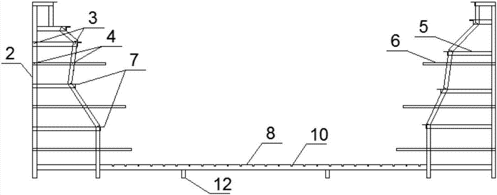
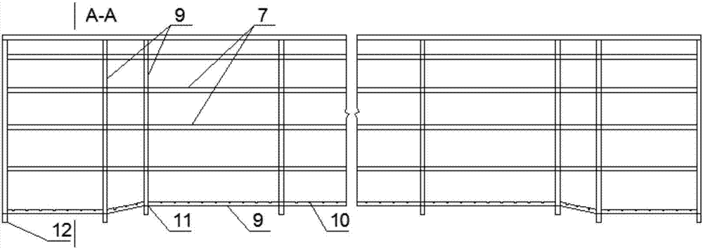
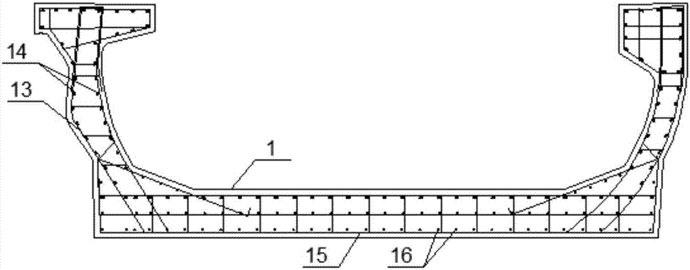
[0039] Explanation of terms: the support member refers to a plurality of support columns; the variable section a...


PUM


Abstract

The invention discloses an adjustable prefabricated U-shaped beam steel bar binding clamping fixture and a construction method. The adjustable prefabricated U-shaped beam steel bar binding clamping fixture comprises two supporting frames which are connected through bottom plate transverse beams; bottom plate longitudinal beams are welded to the bottom plate transverse beams and longitudinally connected with the multiple bottom plate transverse beams, and the bottom plate longitudinal beams and the bottom plate transverse beams form a stable latticed structure; web transverse beam sleeves and auxiliary erection bar sleeves are horizontally welded to the supporting frames, and web transverse beams and auxiliary erection bars penetrate through the web transverse beam sleeves and the auxiliary erection bar sleeves correspondingly, then are exposed out of the inner sides of the supporting frames by a distance, and are temporarily welded to the supporting frames; web longitudinal beams are welded to the exposed ends of the web transverse beams and the exposed ends of the auxiliary erection bars; positioning grooves are formed in the web longitudinal beams, the bottom plate transverse beams and the bottom plate longitudinal beams and serve as opening grooves in the beams; variable cross-section adjusting pieces are used as temporary welding pieces and are temporarily welded to the bottom plate longitudinal beams and the bottom plate transverse beams according to the length of U-shaped beams, and the variable cross-section position of the whole clamping fixture is adjusted; and supporting pieces are welded to the bottoms of the supporting frames and the bottoms of the bottom plate transverse beams.

Description

technical field [0001] The invention relates to the technical field of bridges used in civil engineering, and more particularly relates to an adjustable prefabricated U-shaped beam steel bar binding mold and a construction method. Background technique [0002] With the rapid development of urbanization and the increasing population of our country, urban rail transit has increasingly become a problem that people pay attention to. U-shaped girder is a relatively novel elevated bridge structure form adopted by my country's urban rail transit in recent years. The edge plate forms a "U"-shaped cross-section, which has the advantages of light structure, good noise reduction effect, low building height, high space utilization, safe driving, and beautiful appearance. [0003] Although the U-shaped beam has many advantages, in order to make the structure more beautiful, the "U"-shaped structural section web is generally designed as a circular arc; at the same time, unlike the traditi...

Claims


Application Information

Patent Timeline
IPC IPC(8): B28B23/02
CPCB28B23/02
Inventor 丛义营王鹏刘博张丙东刘波吴大庆张荣伦李宗田李海伟董旭孙国富
Owner THE FIFTH PROJECT OF CHINA RAILWAY BUREAU 14 GROUP
Why Eureka
Try Eureka