Fine sand sorting machine

A sorting machine and fine sand technology, applied in flotation water/sewage treatment, packaging, etc., can solve problems such as residue and equipment corrosion, and achieve the effect of prolonging service life and thorough sand discharge.

Pending Publication Date: 2017-09-22
重庆耐德生态科技有限公司
View PDF4 Cites 3 Cited by
  • Summary
  • Abstract
  • Description
  • Claims
  • Application Information

AI Technical Summary

Problems solved by technology

[0004] Aiming at the deficiencies in the prior art, the present invention provides a vortex concave air flotation machine, which solves the problem of

Method used


Image

  • Fine sand sorting machine
  • Fine sand sorting machine
  • Fine sand sorting machine

Examples


Example Embodiment

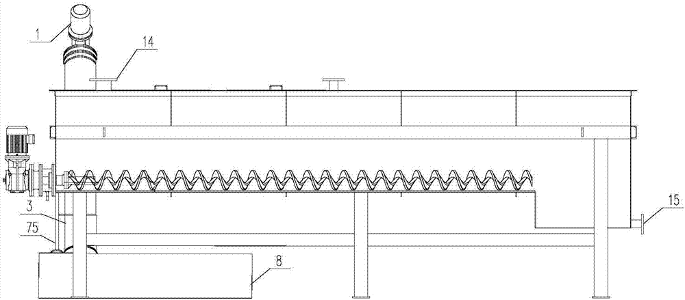
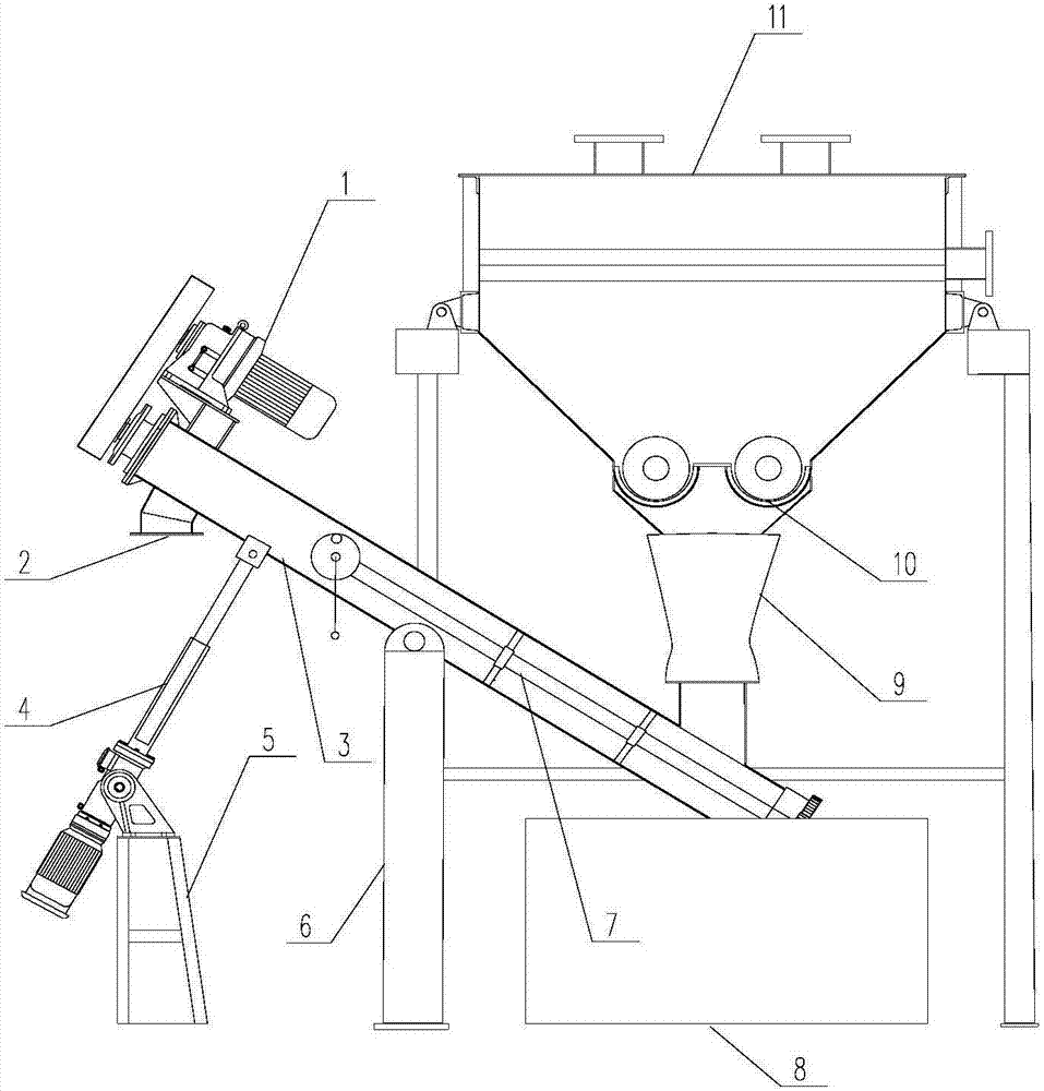
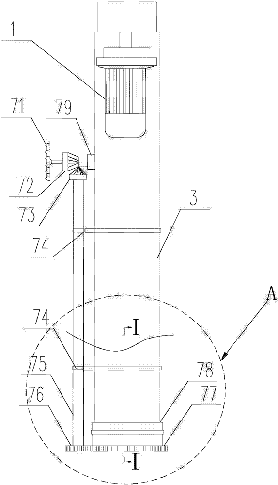
[0018] figure 1 The shown fine sand separator includes a first screw conveyor, a second screw conveyor, a sand-water separation box 11 and a sand discharge mechanism; a slurry inlet 14 is opened on the top of one end of the sand-water separation box 11, The sand-water separation box 11 is provided with a water baffle (not marked in the figure), the water baffle is installed on the inner wall of the sand-water separation box 11 through a mounting frame, and the water baffle is located directly below the slurry inlet 14, so that the The slurry entering the slurry inlet 14 can only impact on the water retaining plate, and an overflow plate (not marked in the figure) is erected on the bottom surface of one end of the sand-water separation box 11. The overflow plate separates the inner cavity of the sand-water separation box 11 into turbid water. The top of the turbid water cavity is connected with the top of the clean water cavity. The clean water cavity is located at the end of t...


PUM


Abstract

The invention provides a fine sand sorting machine. The machine comprises a first spiral conveyor, a second spiral conveyor, a sand and water separation box body and a sand discharge mechanism; a seriflux inlet is formed in the top portion of one end of the sand and water separation box body, a water retaining plate is arranged in the sand and water separation box body, and the water retaining plate is located under the seriflux inlet, so that seriflux which enters from the seriflux inlet can only impact on the water retaining plate; a water outlet which is communicated with the bottom of a clear water cavity is formed in the sand and water separation box body, the first spiral conveyor and the second spiral conveyor which are located on the bottom of a muddy water cavity are arranged in the sand and water separation box body, and a flexible pipe which is located below the seriflux inlet is arranged in the sand and water separation box body; the first spiral conveyor and the second spiral conveyor are all used for transporting fine sand of the bottom of the muddy water cavity to the flexible pipe, and the flexible pipe transports the fine sand to the sand discharge mechanism which is located below the sand and water separation box body. The fine sand sorting machine has the advantages that through third rotary-type spiral transport tubes, sand discharge is more thorough, and the electricity usage amount is reduced, the energy is saved, and the cost is lowered; the survival life of the device is prolonged by a slag discharge device.

Description

technical field [0001] The invention relates to the field of sewage treatment equipment, in particular to a fine sand separator. Background technique [0002] In the field of environmental protection, it is sometimes necessary to separate the fine sand from water, collect the fine sand, and then collect the sewage, and the fine sand separator comes in handy. The sand discharge mechanism is a part of the fine sand separator, which is used to lift the fine sand and separate it from water, so it plays a vital role. [0003] In the prior art, there are currently the following deficiencies: due to the difference in the thickness of the slurry entering the slurry separation device (the previous process of the sand discharge mechanism), the sand discharge mechanism of the fine sand separator is usually fixed beside the fine sand separator. , The sand discharge mechanism includes a sand discharge pipe with an inclined setting. Because the sand discharge pipe is fixed, it is impossi...

Claims


Application Information

Patent Timeline
IPC IPC(8): C02F1/24B65G33/24
CPCB65G33/24C02F1/24
Inventor 宋淼王海云杨林波刘洋瞿忠卫洪超颖杨华王耀波邓兆娟
Owner 重庆耐德生态科技有限公司
Why Eureka
Try Eureka