Bridge concrete pouring attachment type vibrating and tamping device

A vibrating device and concrete technology, which is applied in bridges, bridge construction, erection/assembly of bridges, etc., can solve the problems of difficulty in installation, commissioning and unloading, low reuse efficiency, high risk factor, etc., and achieves convenient and quick installation, commissioning and disassembly, and simple structure High efficiency and high safety factor

Inactive Publication Date: 2017-09-22
吴蕴仪
View PDF0 Cites 8 Cited by
  • Summary
  • Abstract
  • Description
  • Claims
  • Application Information

AI Technical Summary

Problems solved by technology

[0003] Traditional bridge concrete pouring, due to the large working area, the traditional vibrator cannot vibrate deeply to ensure the quality of pouring, and it is difficult to install and debug. It is often disassembled after the concrete is solidified, and the reuse efficiency is low. Problems such as personnel operation and high risk factor restrict its use and development
[0004] In order to solve the above problems, the present invention is proposed, which overcomes the traditional bridge concrete pouring. Due to the large volume of bridge concrete pouring, the traditional vibrating device has poor vibrating effect due to the narrow vibration working surface, which cannot meet the special operation of the bridge. It solves the problem that the traditional bridge concrete pouring and vibrating device is complicated in structure design and difficult to install, debug and unload, which results in time-consuming and labor-intensive use in actual use, which seriously affects the progress of the work. The problem of dangerous accidents caused by surface operation, through the design of the fastening installation module and the attached vibrating module, the present invention has simple and efficient structure, convenient and fast installation, debugging and disassembly, good vibration effect, high safety factor, stable transmission, etc. advantage

Method used


Image

  • Bridge concrete pouring attachment type vibrating and tamping device
  • Bridge concrete pouring attachment type vibrating and tamping device
  • Bridge concrete pouring attachment type vibrating and tamping device

Examples


Embodiment Construction

[0022] The following will clearly and completely describe the technical solutions in the embodiments of the present invention with reference to the accompanying drawings in the embodiments of the present invention. Obviously, the described embodiments are only some, not all, embodiments of the present invention. Based on the embodiments of the present invention, all other embodiments obtained by persons of ordinary skill in the art without making creative efforts belong to the protection scope of the present invention.

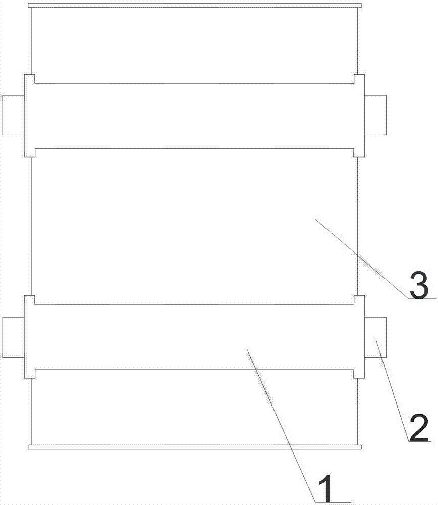
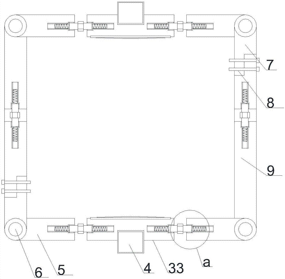
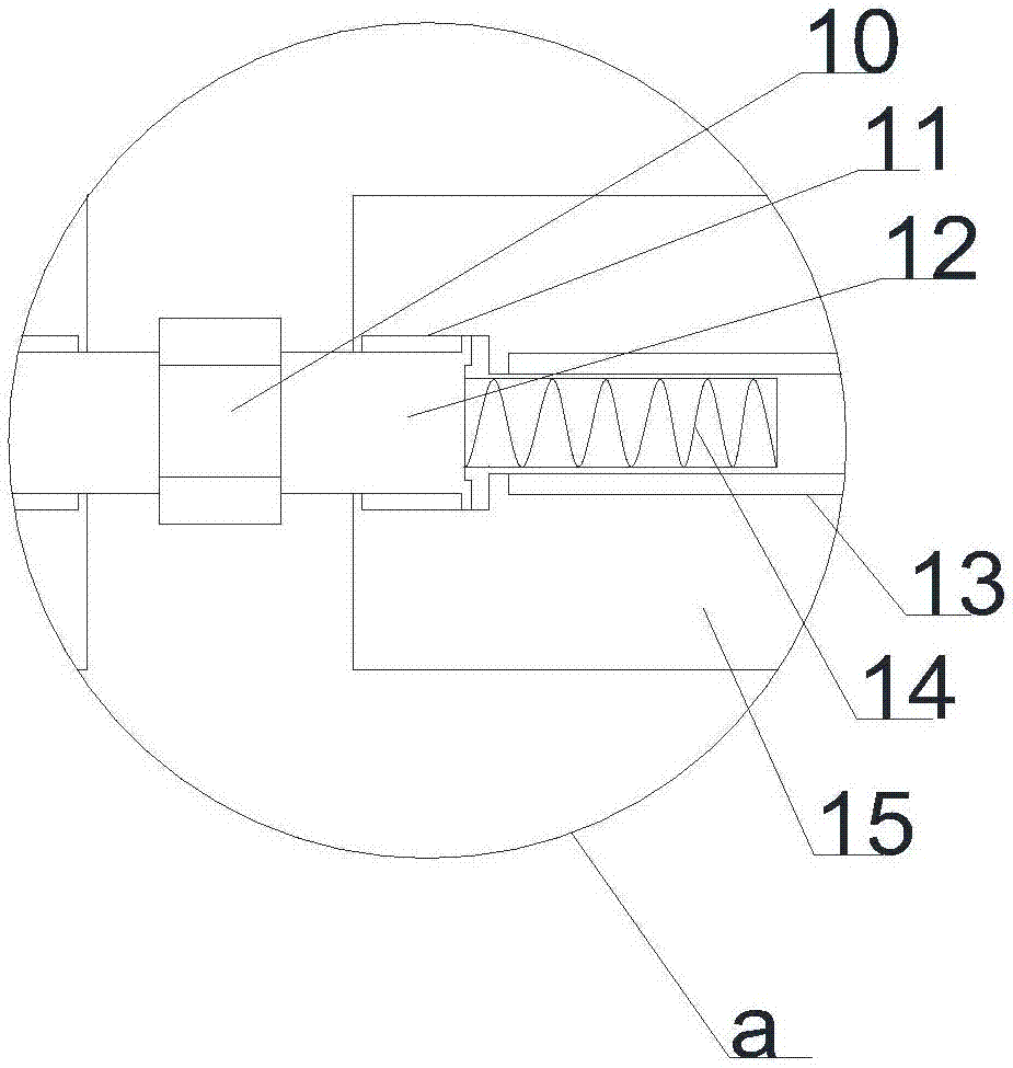
[0023] see Figure 1-7 , in an embodiment of the present invention, an attached vibrating device for bridge concrete pouring, including a concrete pouring formwork and a fastening installation module and an attached vibrating module installed outside the package, the concrete pouring formwork includes a four-sided prefabricated package set Plate 3, the upper and lower ends of the four-sided pre-supported plate 3 are provided with anti-seepage rubber belts, and...


PUM


Abstract

The invention discloses an attached vibrating device for bridge concrete pouring, which includes a concrete pouring formwork and a fastening installation module and an attached vibrating module installed outside it. The outer side of the pre-support plate is fastened with a fastening installation module. The fastening installation module includes a telescopic installation mechanism arranged symmetrically on the left and right, and a telescopic fastening mechanism arranged symmetrically on the front and back through the connection of the installation shaft. The attached vibrating module is arranged symmetrically on the Fasten the upper and lower sides of the installation module. The attached vibrating module includes a Y-axis vibrator inlaid on the upper end of the upper main telescopic installation plate and the lower end of the lower main telescopic installation plate. The present invention has a simple structure High efficiency, convenient and fast installation, debugging and disassembly, good vibrating effect, high safety factor, stable transmission and so on.

Description

technical field [0001] The invention relates to bridge concrete vibrating equipment, in particular to an attached vibrating device for bridge concrete pouring. Background technique [0002] When using a concrete mixer to mix the concrete components, it is necessary to remove the air bubbles and tamp them to make the concrete compact and eliminate the honeycomb surface of the concrete, so as to improve its strength and ensure the quality of the concrete components. Concrete vibration A machine is a machine for mechanized compaction of concrete. [0003] Traditional bridge concrete pouring, due to the large working area, the traditional vibrator cannot vibrate deeply to ensure the quality of pouring, and it is difficult to install and debug. It is often disassembled after the concrete is solidified, and the reuse efficiency is low. Problems such as personnel operation and high risk factor have restricted its use and development. [0004] In order to solve the above problems,...

Claims


Application Information

Patent Timeline
Patent Type & Authority Applications(China)
IPC IPC(8): E01D21/00
CPCE01D21/00
Inventor 吴蕴仪
Owner 吴蕴仪
Why Eureka
Try Eureka