Highway protective device

A technology for protective devices and highways, applied in the direction of road safety devices, roads, roads, etc., can solve the problems of increasing the degree of damage to the vehicle itself, the protection and protection of the life safety of the driver and passengers in the car, etc., and achieve structural Simple, good cushioning effect, and the effect of improving survival rate

Active Publication Date: 2017-09-22
孙树才
View PDF5 Cites 4 Cited by
  • Summary
  • Abstract
  • Description
  • Claims
  • Application Information

AI Technical Summary

Problems solved by technology

[0002] At present, guardrails are usually set up on the expressway to play a safety role. When a high-speed vehicle runs out of control and hits the guardrail of the expressway, the guardrail can block or partially offset the impact caused by the impact through its own deformation. Huge damage force, although the current guardrail has a certain effect in preventing excessive displacement of vehicles, but when the vehicle is driving, the existing guardrail cannot effectively warn the vehicles on the road. It can play a protective role after the accident, not only cannot effectively reduce the probability of accidents, but also because the current guardrail is usually made of steel with high rigidity and strength, its structure is very simple, the material hardness is relatively high, and at the same time it is brittle It is also large. When receiving an excessive impact force, the change of its critical tension mainly depends on the properties of the steel material. The structure and design characteristics of the existing guardrails also lead to the fact that the existing guardrails can only play a role in the process of use. However, this protection method will not only increase the degree of damage to the vehicle itself after the vehicle is hit, but also hardly protect and guarantee the life safety of the driver and passengers in the vehicle. Obviously, the existing Highway guards fail to meet people's needs more effectively

Method used


Image

  • Highway protective device
  • Highway protective device
  • Highway protective device

Examples


Embodiment Construction

[0022] In order to clearly illustrate the technical features of this solution, the present invention will be described in detail below through specific implementation modes and in conjunction with the accompanying drawings.

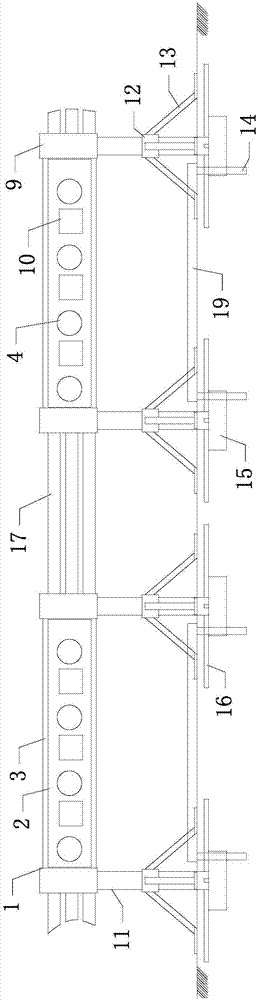
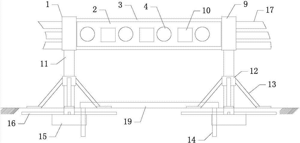
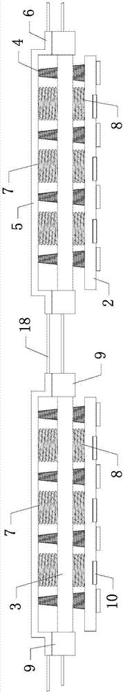
[0023] Such as Figure 1-6 As shown in , a highway protection device includes a plurality of interconnected protection splits 1, and the protection split 1 includes an upper protection device, and a support device is respectively provided at the bottom of both sides of the upper protection device, and the support device The bottom of each protective split body 1 is provided with a bottom fixing device arranged below the foundation, and the adjacent upper protective devices of each protective split body 1 are connected through a buffer connection device, and the bottom fixing devices of each adjacent protective split body 1 are respectively It is fixed on the foundation by a fastening connection device.

[0024] The upper protection device includes a hori...


PUM


Abstract

The invention relates to the field of highway facilities, in particular to a highway protective device. The highway protective device comprises multiple mutually connected protective separate bodies, each protective separate body comprises an upper layer protective device, support devices are arranged on the bottoms of the two sides of the upper layer protective device, a bottom fixture arranged below a foundation is arranged at the bottom of each support device, the adjacent upper layer protective devices of the protective separate bodies are connected through buffer connecting devices, and the bottom fixtures of the adjacent protective separate bodies are fixedly connected to the foundation through fastening connection devices. The highway protective device is simple in structure and reasonable in design and can play a role of warning drivers during daytime and nighttime through a warning board, by means of the protective separate bodies, the protective and buffer effects on a vehicle can be achieved when the vehicle strikes the device, the requirements of people are effectively met, and the problems existing in the prior art are solved.

Description

Technical field: [0001] The invention relates to the field of highway facilities, in particular to a highway protection device. Background technique: [0002] At present, guardrails are usually set up on the expressway to play a safety role. When a high-speed vehicle runs out of control and hits the guardrail of the expressway, the guardrail can block or partially offset the impact caused by the impact through its own deformation. Huge damage force, although the current guardrail has a certain effect in preventing excessive displacement of vehicles, but when the vehicle is driving, the existing guardrail cannot effectively warn the vehicles on the road. It can play a protective role after the accident, not only cannot effectively reduce the probability of accidents, but also because the current guardrail is usually made of steel with high rigidity and strength, its structure is very simple, the material hardness is relatively high, and at the same time it is brittle It is a...

Claims


Application Information

Patent Timeline
Patent Type & Authority Applications(China)
IPC IPC(8): E01F15/02E01F9/619E01F9/669
CPCE01F9/619E01F9/669E01F15/04E01F15/0461Y02A30/30
Inventor 孙树才
Owner 孙树才
Why Eureka
Try Eureka