

Fuel cell stack
a technology of fuel cell stack and stack body, which is applied in the direction of fuel cells, cell components, fuel cell grouping, etc., can solve the problems of insufficient tightening load applied to the stack body, inability to maintain the desired tightening load in the stacking direction, and easy deformation of the outer shape of the stack body, etc., and achieves the effect of simple structur
- Summary
- Abstract
- Description
- Claims
- Application Information
AI Technical Summary
Benefits of technology
Problems solved by technology
Method used
Image

Examples
first embodiment
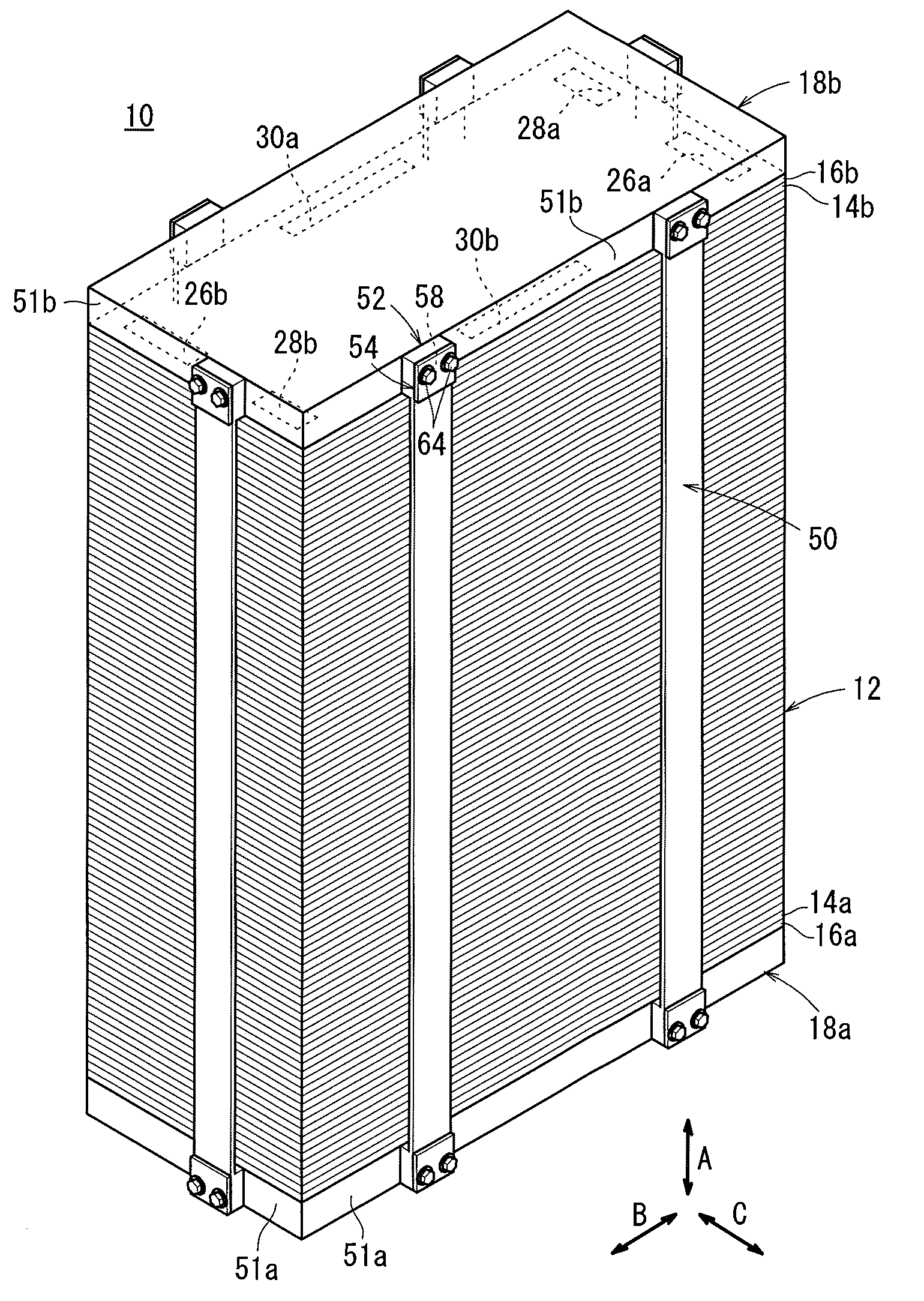
[0024]As shown in FIG. 1, a fuel cell stack 10 according to the present invention is formed by stacking a plurality of fuel cells 12 in a vertical direction indicated by an arrow A. At opposite ends of the fuel cells 12 in the stacking direction, terminal plates 14a, 14b are provided. Insulating plates 16a, 16b are provided outside the terminal plates 14a, 14b. Further, end plates 18a, 18b are provided outside the insulating plates 16a, 16b.
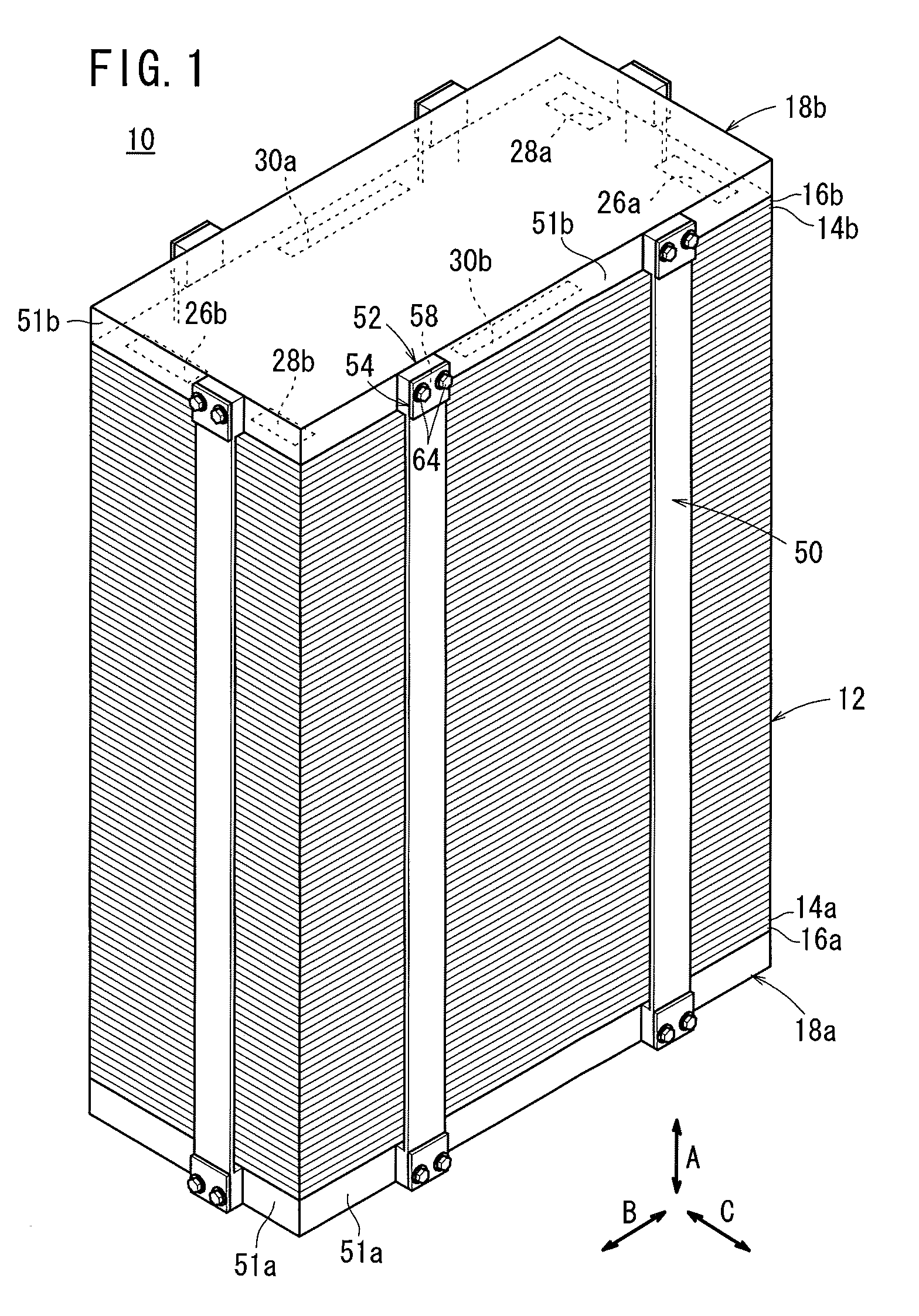
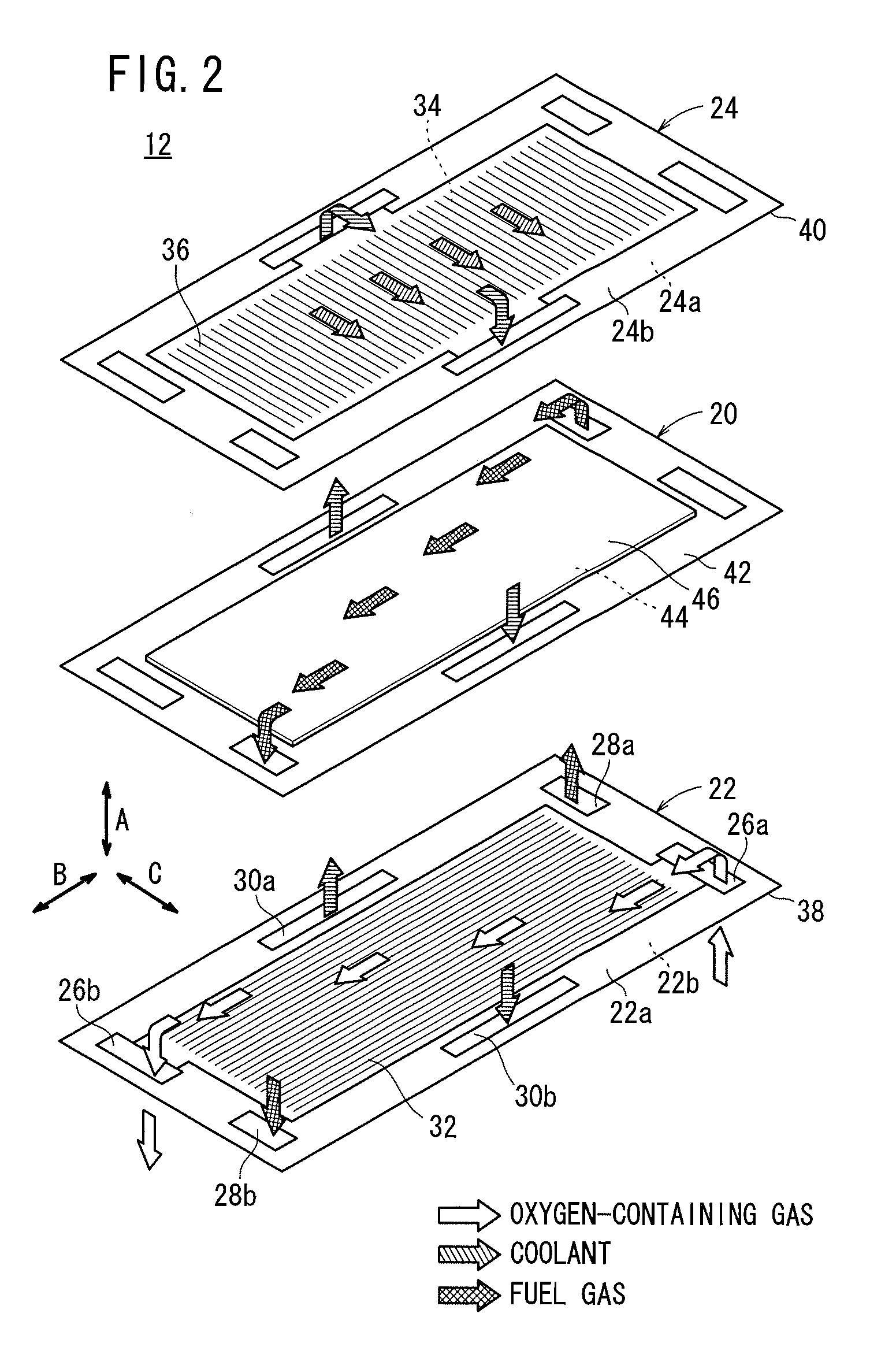
[0025]As shown in FIG. 2, each of the fuel cells 12 includes a membrane electrode assembly 20, and first and second separators 22, 24 sandwiching the membrane electrode assembly 20. For example, the first separator 22 and the second separator 24 are metal separators of steel plates, stainless steel plates, aluminum plates, or plated steel sheets. Alternatively, carbon separators may be used as the first and second separators 22, 24.
[0026]At one end of the fuel cell 12 in a horizontal direction indicated by an arrow B in FIG. 2, an oxygen-contain...
second embodiment
[0066]In the second embodiment, the extension 90 provided at each of both ends in the longitudinal direction of the coupling member 82 is attached across the projection 88 provided in the end plate 18a or the end plate 18b. Therefore, the projection 88 and the extension 90 abut against each other, and tension in the tightening direction is applied to the fuel cell stack 80.
[0067]In the structure, the tightening force for tightening the coupling members 82 and the end plates 18a, 18b is maintained by the fixing mechanisms 86. Thus, in the second embodiment, the same advantages as in the first embodiment are obtained. Further, the distance between the end plates 18a, 18b can be adjusted by the coupling members 82 and the holding mechanisms 84.
PUM
| Property | Measurement | Unit |
|---|---|---|
| tension | aaaaa | aaaaa |
| power generation performance | aaaaa | aaaaa |
| pressure | aaaaa | aaaaa |
Abstract
Description
Claims
Application Information