Water pump

A water pump and pump cover technology, applied in the direction of pumps, pump devices, pump components, etc., can solve the problems of water resource waste, cooling water loss, unfavorable pump lift lift, etc., and achieve the effect of easy flow and improved connection firmness.

Active Publication Date: 2017-09-22
宁波天安汽车零部件有限公司
View PDF12 Cites 6 Cited by
  • Summary
  • Abstract
  • Description
  • Claims
  • Application Information

AI Technical Summary

Problems solved by technology

In this way, it is easy to cause a large loss of mechanical energy of the cooling water during the mixing process, which is not conducive to the improvement of the lift of the water pump, and it is easy to cause waste of water resources.

Method used


Image

  • Water pump
  • Water pump
  • Water pump

Examples


Embodiment 1

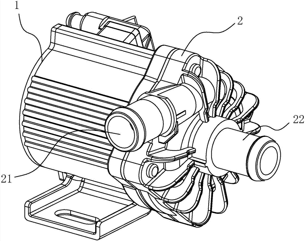
[0041] as attached figure 1 As shown, a water pump includes a pump body 1 and a pump cover 2. The pump cover 2 is covered at one end of the pump body 1. The two are fixed together by bolts from the direction of the four corners of the square, and the pump The center of the cover 2 has a water inlet 22, and the peripheral surface of the pump cover 2 has a water outlet 21.

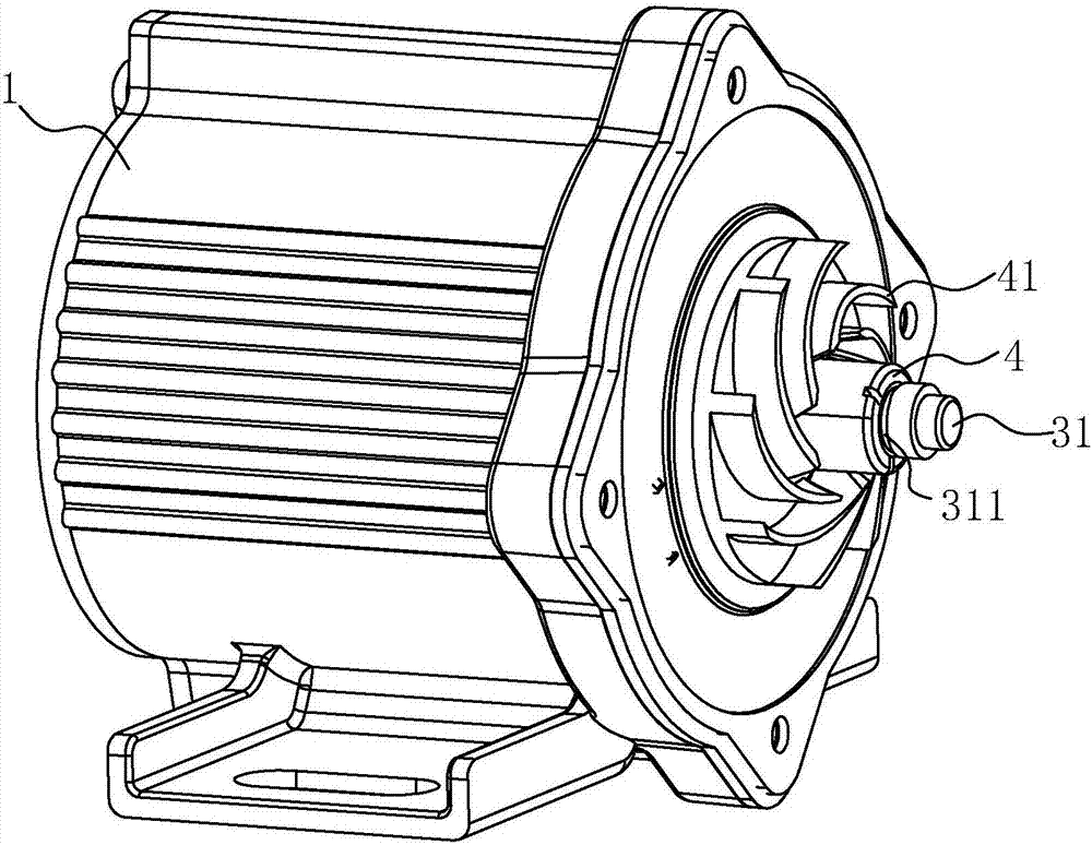
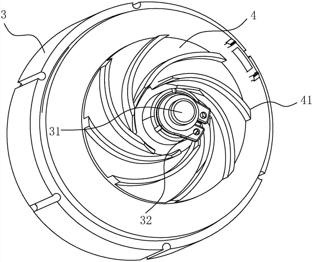
[0042] Here, as attached figure 2 And attached image 3 As shown, the inside of the pump body 1 is provided with a motor 3 , and the output shaft 31 of the motor 3 is located between the pump cover 2 and the pump body 1 . At the same time, the output shaft 31 is also sleeved with the impeller 4 between the pump body 1 and the pump cover 2, and an annular groove 311 is opened on the peripheral surface of the output shaft 31 near its end, and a stop ring 32 is embedded in the annular groove 311. , the limit ring 32 can abut against the impeller 4 , so that the impeller 4 can rotate stably driven by the out...

Embodiment 2

[0050] as attached Figure 10 As shown, a water pump, based on the first embodiment, the pump body 1 has a cavity 11 between the bottom of the side away from the pump cover 2 and the motor 3, and the cavity 11 can improve the heat dissipation function of the motor 3 on the one hand. On the other hand, it can also play a certain buffering role, which is beneficial to reduce the vibration damage of the water pump.


PUM


Abstract

A water pump comprises a pump body and a pump cover arranged on the pump body in a covering manner. A water inlet is formed at the center of the pump cover. A water outlet is formed in the circumferential face of the pump cover. A motor is arranged in the pump body. An output shaft of the motor is sleeved with an impeller located in the pump cover. The impeller is provided with a plurality of blades. The impeller is provided with a circular-truncated-cone-shaped shade body. The center of the shade body is provided with a through hole. The through hole corresponds to the water inlet. The edge of the side, where the impeller is located, of the shade body is turnup towards the side where the pump cover is located, and cooling water not entering the shade body here flows along the surface of the shade body. Hereby, due to the fact that the edge of the side, close to the impeller, of the shade body is turnup towards the side where the pump cover is located, the cooling water which is thrown away along the surface of the shade body can move along the side far away from the pump body, and a water film is formed between the shade body and the pump cover; and in this way, the situation that the cooling water not entering the space between the shade body and the impeller enters an output flow channel to be mixed with pressurized cooling water, and then the lift of the finally conveyed cooling water is lowered is prevented beneficially.

Description

technical field [0001] The invention relates to the field of liquid conveying equipment, in particular to a water pump. Background technique [0002] With the continuous improvement of the economic level, cars have entered thousands of households. With the continuous increase of the number of cars, the requirements for engines are getting higher and higher. The power of modern car engines is getting bigger and bigger, and the technological level of engines is also getting better The higher the temperature, the higher the efficiency of work and the higher the heat dissipation requirements. The water pump is a very important part for the engine of a car. It can deliver coolant to the cylinder block of the engine, and after the coolant flows through the surface of the cylinder block, it will take away the heat of the cylinder block, so as to ensure that the engine normal operation. Therefore, the role of the water pump is also increasingly important, and the water pump plays ...

Claims


Application Information

Patent Timeline
Patent Type & Authority Applications(China)
IPC IPC(8): F04D13/06F04D29/42F04D29/22F04D29/24F04D29/20F04D29/58
CPCF04D13/06F04D29/20F04D29/2222F04D29/242F04D29/426F04D29/586
Inventor 毛利敏
Owner 宁波天安汽车零部件有限公司
Why Eureka
Try Eureka