
Gear mechanism for worm and gear drive

A technology of gear mechanism and worm gear, which is applied in the direction of gear transmission, belt/chain/gear, mechanical equipment, etc., can solve the problems of inconvenient drive control, etc., and achieve the effect of convenient drive control and good stability

Inactive Publication Date: 2017-09-22
SUZHOU HEYER PRECISION CO LTD
View PDF0 Cites 0 Cited by
  • Summary
  • Abstract
  • Description
  • Claims
  • Application Information

AI Technical Summary

Problems solved by technology

Existing worm and gear mechanisms are inconvenient for drive control

Method used


Image

  • Gear mechanism for worm and gear drive

Examples


Embodiment Construction

[0012] In order to make the technical means, creative features, goals and effects achieved by the present invention easy to understand, the present invention will be further described below in conjunction with specific embodiments.

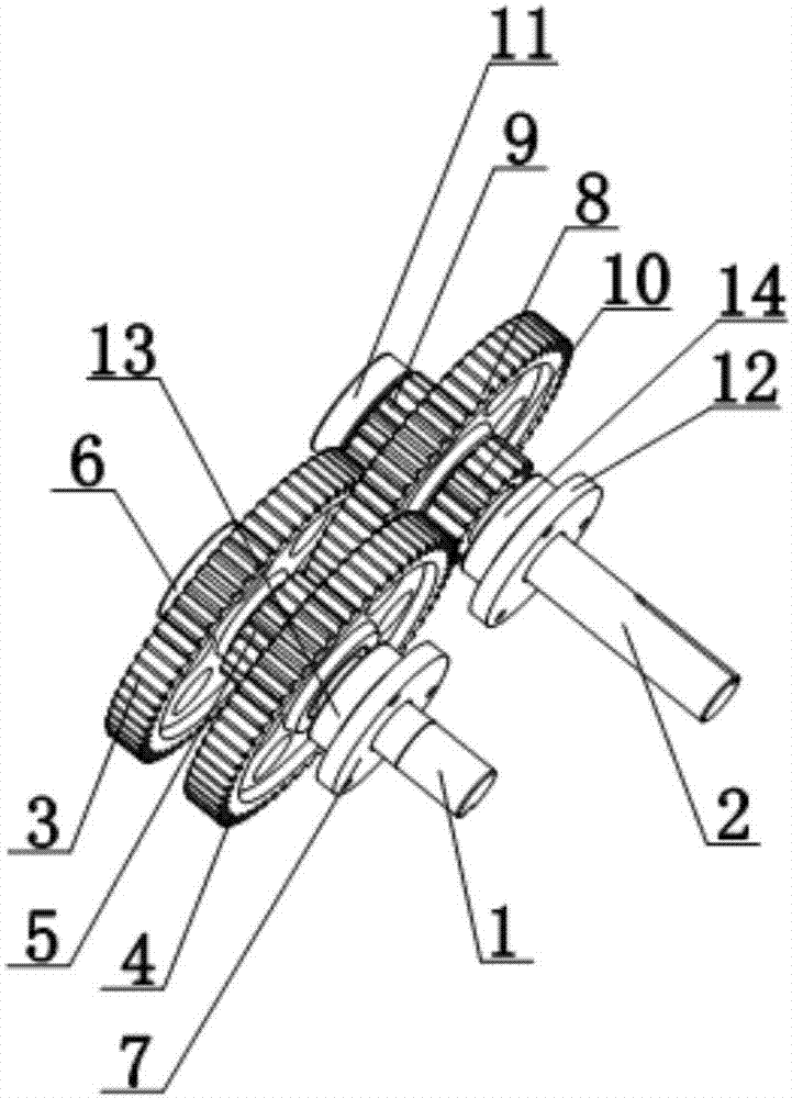
[0013] Such as figure 1 As shown, a gear mechanism for driving worm gears includes a rotating shaft 1 and a driven shaft 2. The outer peripheral surface of the rotating shaft 1 is fitted with a first driving gear 3, a second driving gear 4 and a first transmission gear 5. The transmission gear 5 is installed between the first driving gear 3 and the second driving gear 4, and the outer peripheral surface of the driven shaft 2 is covered with the second transmission gear 8, the first driven gear 9 and the second driven gear 10. The transmission gear 8 is installed between the first driven gear 9 and the second driven gear 10, the first driving gear 3 meshes with the first driven gear 9, the second driving gear 4 meshes with the second driven gear 10...


PUM


Abstract

The invention discloses a gear mechanism for driving worm gears, which includes a rotating shaft and a driven shaft. The outer peripheral surface of the rotating shaft is covered with a first driving gear, a second driving gear and a first transmission gear. The first transmission gear is installed on the Between a driving gear and the second driving gear, the outer peripheral surface of the driven shaft is covered with a second transmission gear, a first driven gear and a second driven gear, and the second transmission gear is installed on the first driven gear and the second driven gear. Between the driven gears, the first driving gear meshes with the first driven gear, the second driving gear meshes with the second driven gear, and the first transmission gear meshes with the second transmission gear. The invention can control the worm gear to realize the rotation adjustment through the rotation of the transmission gear, so as to facilitate the drive control of the worm gear.

Description

technical field [0001] The invention relates to a gear mechanism, in particular to a gear mechanism for driving a worm gear. Background technique [0002] Worm gears are commonly used to transmit motion and power between two interleaved shafts. The worm gear and the worm are equivalent to the gear and the rack in their middle plane, and the worm is similar in shape to the screw. The worm wheel is generally made of tin bronze, and the paired worm material is hardened with 45 steel to HRC45~55, or 40Cr hardened to HRC50~55, and then ground to a roughness of Ra0.8μm by a worm grinder. The reducer wears very slowly during normal operation, and some reducers can be used for more than 10 years. If the wear speed is fast, it is necessary to consider whether the selection is correct, whether it is overloaded, and the material of the worm gear, assembly quality or use environment and other reasons. The existing worm gear mechanism is inconvenient for driving control. Contents of...

Claims


Application Information

Patent Timeline
Patent Type & Authority Applications(China)
IPC IPC(8): F16H1/20F16H57/00
CPCF16H1/20F16H57/00
Inventor 黄文卿
Owner SUZHOU HEYER PRECISION CO LTD
Learn More