An outdoor portable portable free-rotating camera pan-tilt bracket

A rotating, camera technology, applied in the machine/stand, camera, camera body, etc., can solve the problems of difficult to carry, inconvenient to use, difficult to pick up, etc., and achieve the effect of reducing the burden on the arm and reducing the size of the body.

Active Publication Date: 2019-01-25
DALIAN JIAOTONG UNIVERSITY
View PDF5 Cites 0 Cited by
  • Summary
  • Abstract
  • Description
  • Claims
  • Application Information

AI Technical Summary

Problems solved by technology

[0002] At present, the camera brackets in the prior art are mainly tripod brackets and monopod brackets. When in use, the bracket feet are opened or directly supported on the ground. For field shooting or mountain climbing photography, the ground is often uneven or muddy. The bulkiness brings a lot of difficulties to taking pictures and carrying. Not only is it difficult to carry, but it is also inconvenient to use. , a camera stand that is easy to carry and can adapt to a variety of shooting environments

Method used


Image

  • An outdoor portable portable free-rotating camera pan-tilt bracket
  • An outdoor portable portable free-rotating camera pan-tilt bracket
  • An outdoor portable portable free-rotating camera pan-tilt bracket

Examples


Embodiment 1

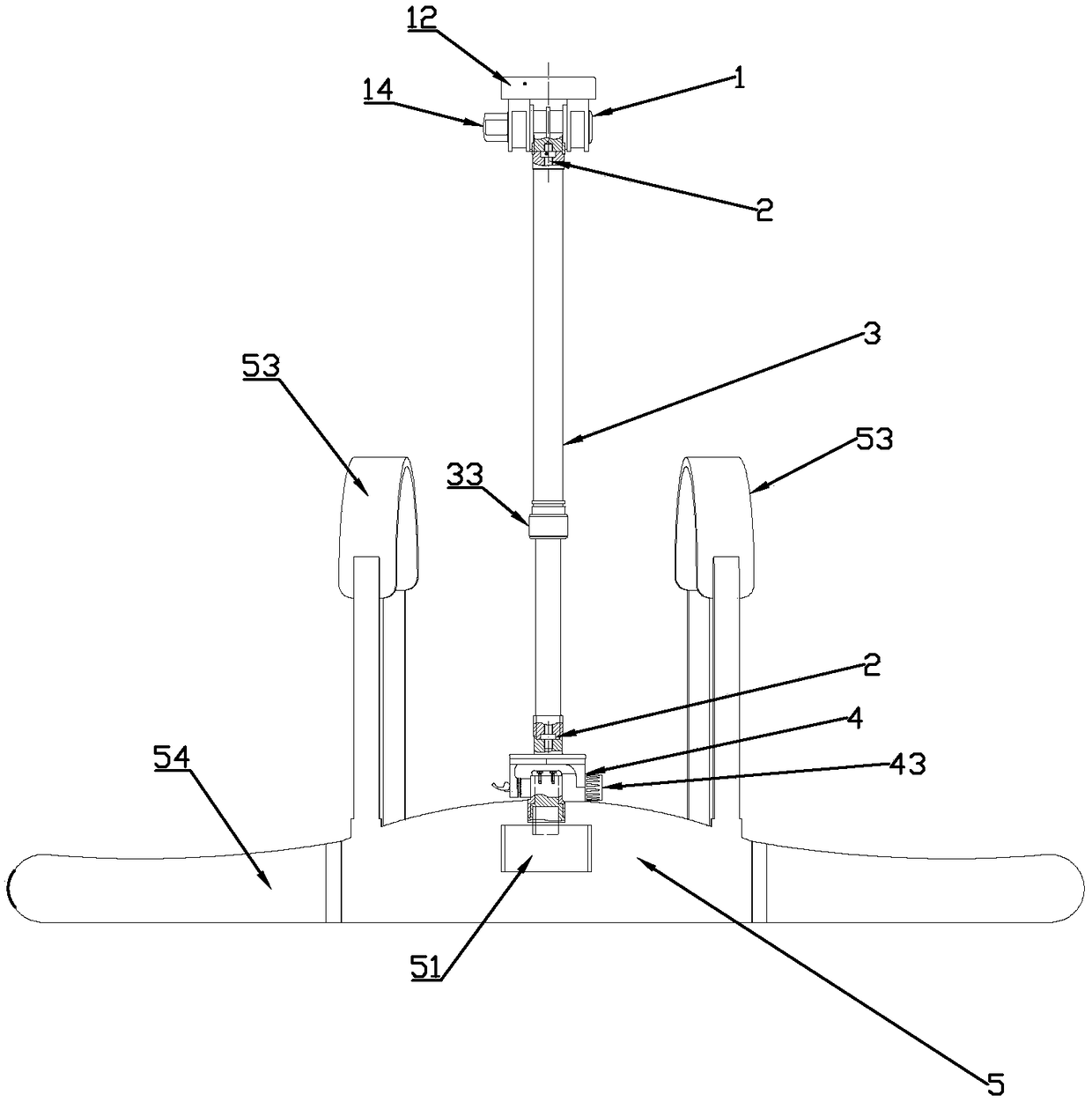
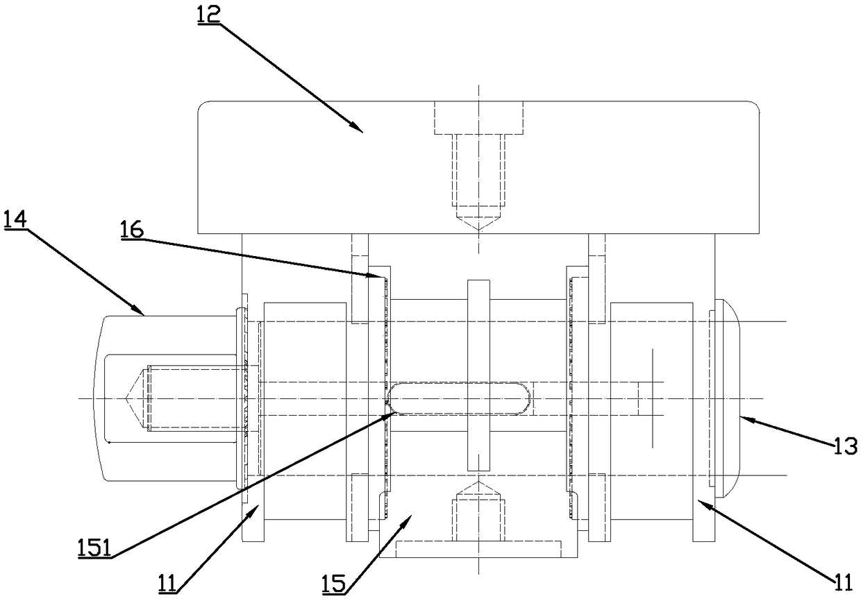
[0029] Such as Figure 1 to Figure 7 As shown, an outdoor portable portable free-rotating camera pan-tilt bracket includes a steering pan-tilt device 1, a stud bolt 2, a spring tightening telescopic rod 3, a free-rotation connection mechanism 4 and a photographic frame portable belt 5;

[0030] Described steering pan-tilt device 1 comprises pan-tilt connecting plate 11, camera pan-tilt 12, locking shaft 13, locking wrench 14 and joint connection seat 15, two described pan-tilt connecting plates 11 upper ends are respectively fixedly connected to the The lower surface of the camera cloud platform 12, the bottom of the cloud platform connecting plate 11 is provided with a groove, the joint connection seat 15 is fitted between the two described cloud platform connecting plates 11, and the locking shaft 13 passes through the The pan-tilt connecting plate 11 and the joint connecting seat 15, the end of the locking shaft 13 is threadedly connected to the locking wrench 14, and the l...

Embodiment 2

[0046] Such as Figure 8 As shown, the difference between this embodiment and Embodiment 1 is that the freely rotating connection mechanism 4 also includes an arched rotating mechanism 49, and the arched rotating mechanism 49 is sleeved on the intermediate rotating shaft 44, so The locking cover 43 and the corresponding protruding structure 491 are rotatably connected to each other, and the locking cover 43 and the corresponding protruding structure 493 have an inclined structure 492 that cooperates with each other.

[0047] The forward and backward movement of the locking cover 43 will cause the corresponding protruding structure 493 to shrink and return. When shrinking, the pressure on the rotating shaft increases, thereby increasing the rotation damping, and correspondingly reducing the rotation damping when returning.

[0048] Due to the adoption of the above technical solution, the present invention relates to an outdoor portable portable free-rotating camera pan-tilt bra...


PUM


Abstract

The invention discloses an outdoor portable portable free-rotating camera pan-tilt bracket, which includes a steering pan-tilt device, a stud bolt, a spring-tightened telescopic rod, a free-rotation connection mechanism and a camera belt; the steering pan-tilt device passes through The stud bolts are connected to the spring-tightened telescopic rod, and the spring-tightened telescopic rod is connected to the free-rotation connection mechanism through a stud bolt, and the free-rotation connection mechanism is connected to the camera belt. . Due to the adoption of the above technical solution, the present invention relates to an outdoor portable portable free-rotating camera pan-tilt bracket, which is small in size and can be carried on the back without being restricted by the terrain; it can be supported on the body to reduce the burden on the arms, and it is convenient to meet the needs of photography Free movement up, down, left, and right is especially convenient for professional photographers who carry heavy cameras.

Description

technical field [0001] The invention relates to the field of camera bracket structures, in particular to an outdoor portable and freely rotatable camera pan-tilt bracket. Background technique [0002] At present, the camera brackets in the prior art are mainly tripod brackets and monopod brackets. When in use, the bracket feet are opened or directly supported on the ground. For field shooting or mountain climbing photography, the ground is often uneven or muddy. The bulkiness brings a lot of difficulties to taking pictures and carrying. Not only is it difficult to carry, but it is also inconvenient to use. , A camera stand that is easy to carry and can adapt to a variety of shooting environments. Contents of the invention [0003] The present invention develops an outdoor portable and freely rotatable camera pan-tilt bracket, which solves the above-mentioned technical problems. [0004] The technical means adopted in the present invention are as follows: an outdoor porta...

Claims


Application Information

Patent Timeline
Patent Type & Authority Patents(China)
IPC IPC(8): F16M13/04F16M11/10F16M11/28G03B17/56
CPCG03B17/561F16M11/10F16M11/28F16M13/04
Inventor 雷蕾李文成姜恒张钊
Owner DALIAN JIAOTONG UNIVERSITY
Why Eureka
Try Eureka