Sampling device

A technology of cutting samples and sample tubes, which is applied in the field of sampling devices, which can solve problems such as too many connecting pipes, air leakage of cutting samples, and decreased sampling efficiency, and achieve the effects of improving the firmness of cooperation, improving the degree of mechanization, and reducing labor intensity

Pending Publication Date: 2017-09-22
GUANGDONG UNIV OF TECH
View PDF4 Cites 2 Cited by
  • Summary
  • Abstract
  • Description
  • Claims
  • Application Information

AI Technical Summary

Problems solved by technology

During the descending process of the existing sample pipe from the deep layer of the grain pile, the connection of the sample pipe is limited by the screw connection. While sucking out the grain grains at the mouth of the nozzle, it moves downward under the action of external force
[0003] However, when the direction of rotation of the sample pipe is opposite to that of the downward movement, the thread at the joint of the sample pipe will become loose, causing the sample pipe to fall off and be buried in the grain pile
At the same time, the existing sampling tube has a simple structure, and it is difficult to change the internal structure of the grain heap and the distribution of the force on the grain heap after the sampling reaches a certain depth, resulting in a limited sampling depth of the sampling tube. , it will be difficult for the sample tube to go down, which will take time and effort; the existing sample tube is connected by threads, and there are many connecting tubes and connection times when deep samples are taken, and it takes a lot of time to tighten the connecting thread. It also takes a lot of time to unscrew the sample tube and disassemble it when disassembling the sample tube
[0004] At the same time, the existing sample tubes need to be disassembled and assembled frequently. After frequent tightening and loosening of the threaded connection, the connecting threads of the sample tubes will be worn, resulting in loose connections and air leakage during sample cutting, resulting in Efficiency drops or even sampling is impossible; the surface of the existing sampling tube is smooth, and as the sampling depth increases, the grain accumulation density in the unit space increases, and the air in the tiny space formed by the contact between the grain and the sampling tube is further compressed, forming a Negative effects of vacuum adsorption lead to difficulty in deep sample cutting, prolonged sample cutting cycle, and high labor intensity for workers

Method used


Image

  • Sampling device
  • Sampling device
  • Sampling device

Examples


Embodiment Construction

[0028] The core of the present invention is to provide a sample cutting device, which can avoid the phenomenon that the sample tube falls off, effectively increase the sample cutting speed, and significantly improve the reliability and service life.

[0029] The following will clearly and completely describe the technical solutions in the embodiments of the present invention with reference to the accompanying drawings in the embodiments of the present invention. Obviously, the described embodiments are only some, not all, embodiments of the present invention. Based on the embodiments of the present invention, all other embodiments obtained by persons of ordinary skill in the art without making creative efforts belong to the protection scope of the present invention.

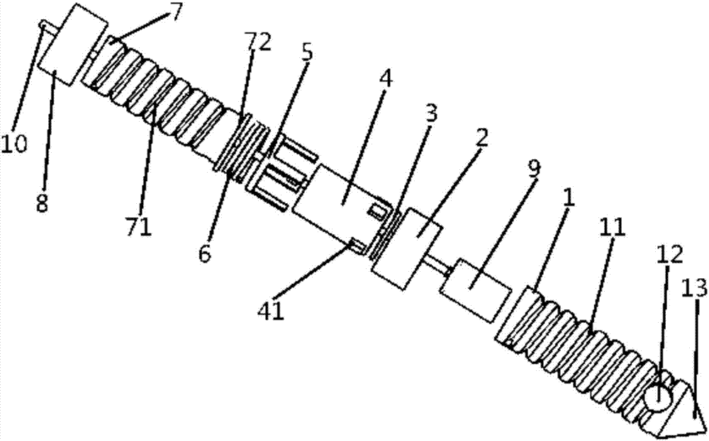
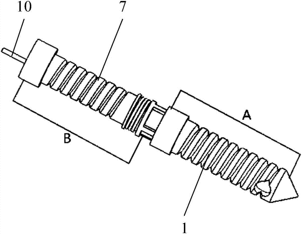
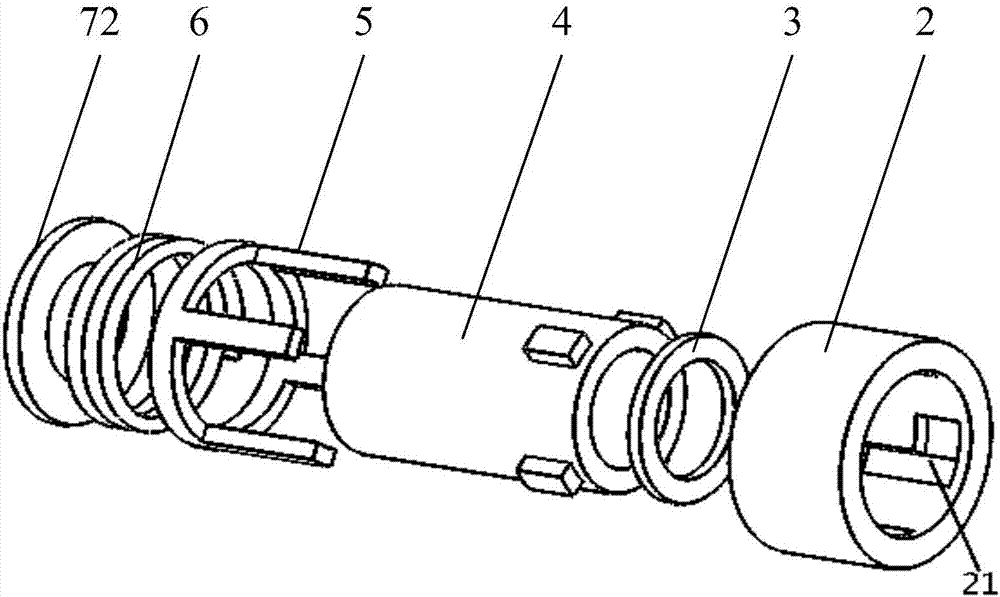
[0030] Please refer to Figure 1 to Figure 6 , figure 1 It is a schematic diagram of the explosion structure of a specific embodiment of the sampling device provided by the present invention; figure 2 It is a ...


PUM


Abstract

The invention discloses a sampling device. The sampling device comprises a main sampling pipe and at least one accessory sampling pipe; the accessory sampling pipe and the main sampling pipe are connected via a locking assembly; the locking assembly comprises a locking female joint and a locking male joint; the locking female joint is provided with a locking groove, and the locking male joint is provided with a locking key capable of realizing matched clamp connection with the locking groove; the locking assembly also comprises a locking buckle used for preventing slipping of the locking key from the locking groove. According to the sampling device, the sampling device is provided with the locking assembly, so that when the main sampling pipe and the accessory sampling pipe are inserted into a grain heap, the whole sampling device is capable of realizing anticlockwise and clockwise moving, losening of the connection part of the main sampling pipe with the accessory sampling pipe is avoided, sampling depth of the sampling pipes are increased effectively, downward movement efficiency of the sampling pipes in sampling process is increased, the reliability of the connection part of the sampling pipes is improved, the service life of the sampling device is prolonged, and rapid connecting and detaching of the main sampling pipe with the accessory sampling pipe can be realized, and sampling time is shortened.

Description

technical field [0001] The invention relates to the field of sample cutting equipment, in particular to a sample cutting device. Background technique [0002] At present, most of the grain sampling tubes sold on the market are ordinary stainless steel light tubes, which are refitted by simple welding. During the descending process of the existing sample pipe from the deep layer of the grain pile, the connection of the sample pipe is limited by the screw connection. While sucking out the grain grains at the mouth of the nozzle, it moves downward under the action of external force at the same time. [0003] However, when the direction of rotation of the sample pipe was opposite to the direction of rotation when going down, the thread at the joint of the sample pipe would become loose, causing the sample pipe to fall off and be buried in the grain pile. At the same time, the existing sampling tube has a simple structure, and it is difficult to change the internal structure of...

Claims


Application Information

Patent Timeline
IPC IPC(8): G01N1/04
CPCG01N1/04Y02E30/30
Inventor 杨杰刘攀张志明李蓉
Owner GUANGDONG UNIV OF TECH
Why Eureka
Try Eureka