Unlock instant, AI-driven research and patent intelligence for your innovation.
Deep sampling equipment for geological detection
What is Al technical title?
Al technical title is built by PatSnap Al team. It summarizes the technical point description of the patent document.
A sampling equipment and deep-layer technology, applied in the direction of sampling devices, etc., can solve the problems of inconvenient portability, large sampling rod size, and inability to perform soil sampling operations, etc.
Inactive Publication Date: 2020-10-20
吴丽梅
View PDF0 Cites 0 Cited by
Summary
Abstract
Description
Claims
Application Information
AI Technical Summary
This helps you quickly interpret patents by identifying the three key elements:
Problems solved by technology
Method used
Benefits of technology
Problems solved by technology
[0003] In the process of geological survey, it is usually necessary to use a drill bit to drill the soil and collect the soil for soil quality testing. The existing geological drilling detection device cannot perform sampling operations on deep geological soil, and the size of the sampling rod is large and inconvenient to carry
Method used
Image
Click on the blue label to locate the original text in one second.
Reading with bidirectional positioning of images and text.
Examples
Embodiment 1
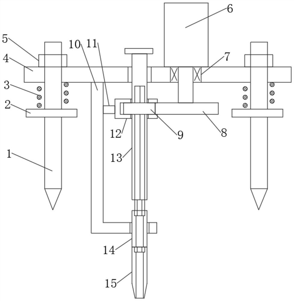
[0028] Such as Figure 1-6 As shown, a kind of deep sampling equipment for geological detection includes a fixed column 1, a step platform 2 is arranged on the fixed column 1, a shock absorbing spring 3 is arranged on the step platform 2, and a Mounting plate 4, described mounting plate 4 is connected with damping spring 3 through lock nut 5, described mounting plate 4 is provided with motor 6, described motor 6 is connected with output shaft, and driving gear 8 is installed on the described output shaft , the driving gear 8 is meshed with the driven gear 9, the driven gear 9 is connected to the limit frame 12, the limit frame 12 is connected to the connecting frame 10 through the connecting column 11, and the connecting frame 10 is set as L-shaped, the driven gear 9 is plugged with a transmission rod 13, the transmission rod 13 is provided with a transmission tooth 130, the top of the transmission rod 13 is provided with a limit block 131, and the transmission rod 13 is conne...
Embodiment 2
[0043] This embodiment is a further improvement and limitation of embodiment 1 on the basis of embodiment 1.
[0044] A deep sampling device for geological detection, including all parts in embodiment 1, and also includes:
[0045] Further, the transmission rod 13 is designed to be solid, and the material of the transmission rod 13 is steel.
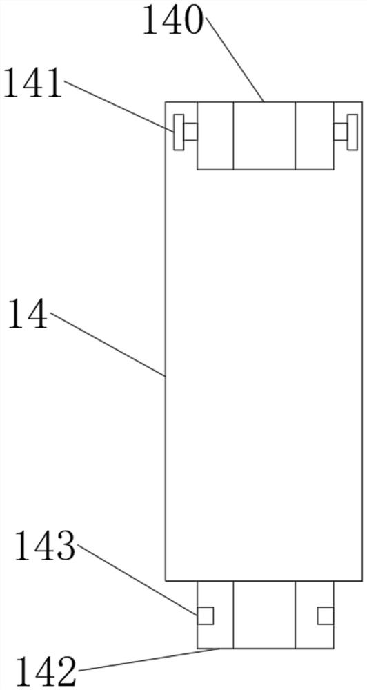
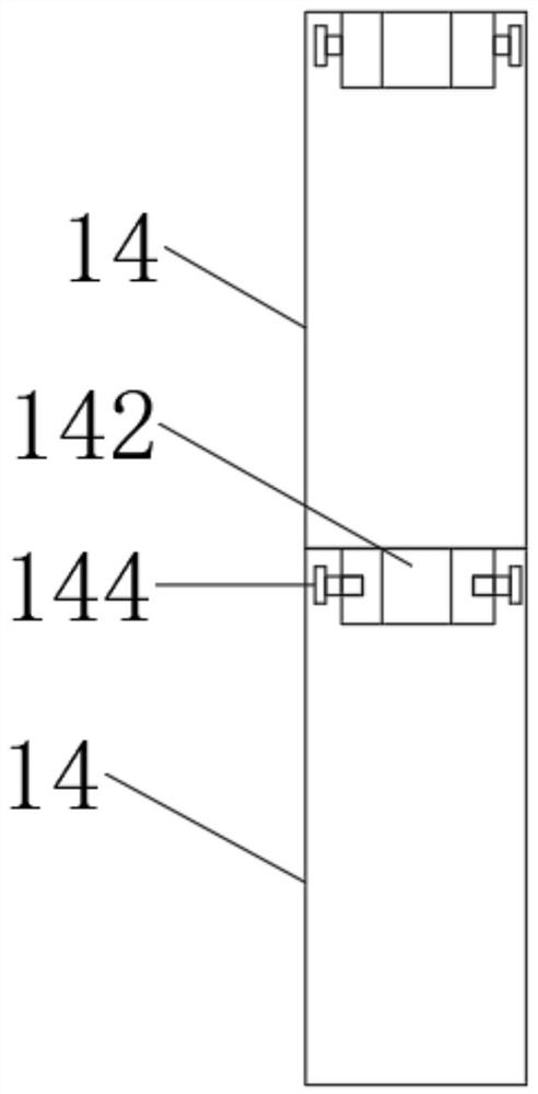
[0046] Concretely, while the transmission rod 13 is transmitting power to the extension rod 14 and the drill bit 15, the transmission rod 13 will continuously descend. Therefore, the transmission rod 13 is set to be solid, and the material of the transmission rod 13 is selected as steel to further improve the quality of the transmission rod 13 .
[0047] The working principle of the embodiment of the present invention is:
[0048] Such as Figure 1-6 As shown, a deep sampling device for geological detection is assembled according to the diagram.
[0049] After the installation is completed, the drive rod 13 is started to rotate by st...
PUM
Abstract
The invention discloses deep sampling equipment for geological detection, relates to the technical field of geological detection sampling detection, and mainly solves the problems that an existing geological detection sampling device is complex in structure, large in sampling rod size and inconvenient to carry. The device comprises a fixed column; a step table is arranged on the fixed column; a damping spring is arranged on the step table; a mounting plate is mounted on the fixed column; the mounting plate is connected with a damping spring through a locking nut; a motor is arranged on the mounting plate; the motor is connected with the output shaft; a driving gear is mounted on the output shaft; the driving gear is meshed with the driven gear; the driven gear is connected with a limitingframe; the limiting frame is connected with a connecting frame through a connecting column; the connecting frame is arranged to be in an L shape; a transmission rod is inserted into the driven gear; the transmission rod is connected with an extension rod; and the extension rod is connected with a drill bit. Large-depth sampling is achieved through the transmission rod, the extension rod and the drill bit.
Description
technical field [0001] The invention relates to the technical field of sampling equipment for geological detection, in particular to deep sampling equipment for geological detection. Background technique [0002] Geological prospecting is the investigation and research activity of conducting geological exploration and detection through various means and methods, determining the appropriate bearing layer, determining the foundation type and calculating the foundation parameters according to the foundation bearing capacity of the bearing layer. It is the discovery of mineral deposits with industrial significance in the general survey of mineral resources. In order to ascertain the quality and quantity of mineral products, as well as the technical conditions for mining and utilization, provide mineral reserves and geological data required for mine construction design, and analyze rocks and strata in a certain area. Conduct investigation and research work on geological condition...
Claims
Application Information
Patent Timeline
Application Date:The date an application was filed.
Publication Date:The date a patent or application was officially published.
First Publication Date:The earliest publication date of a patent with the same application number.
Issue Date:Publication date of the patent grant document.
PCT Entry Date:The Entry date of PCT National Phase.
Estimated Expiry Date:The statutory expiry date of a patent right according to the Patent Law, and it is the longest term of protection that the patent right can achieve without the termination of the patent right due to other reasons(Term extension factor has been taken into account ).
Invalid Date:Actual expiry date is based on effective date or publication date of legal transaction data of invalid patent.

