Paper currency temporary collection device and automatic transaction device

A technology of automatic transaction device and collection device, which is applied to devices for accepting coins, processing coins or valuable banknotes, instruments, etc., can solve problems such as time-consuming, unpredictable banknote jams, and lack of detection devices.

Pending Publication Date: 2017-09-22
SHENZHEN YIHUA COMP +2
View PDF12 Cites 0 Cited by
  • Summary
  • Abstract
  • Description
  • Claims
  • Application Information

AI Technical Summary

Problems solved by technology

[0003] But in the prior art, in the process of temporarily collecting banknotes to the banknote temporary collection device, when an error occurs due to paper jams, the staff needs to manually rotate the operation button to withdraw the banknotes. However, due to the transport in the banknote temporary collection device The roller part and the drum part are two separate parts, and one part can only be rotated with one hand, so in the case of one hand, the two parts must be rotated alternately, which takes a lot of time. If two hands rotate at the same time Two parts, then when both hands are occupied, it is impossible to catch the withdrawn banknote
[0004] At the same time, in the prior art, there is no real-time detection device in the process of transporting the banknotes between the transport roller and the drum, and it is impossible to predict the possibility of paper jams during the transport of the banknotes, and to deal with them in a timely manner. Handle banknotes after they have jammed

Method used


Image

  • Paper currency temporary collection device and automatic transaction device
  • Paper currency temporary collection device and automatic transaction device
  • Paper currency temporary collection device and automatic transaction device

Examples


no. 1 example

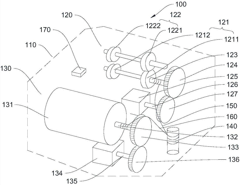
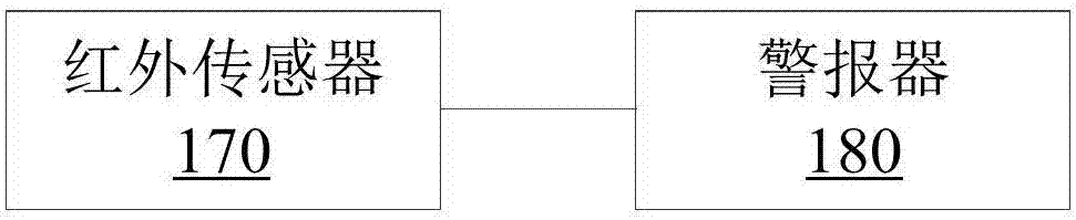
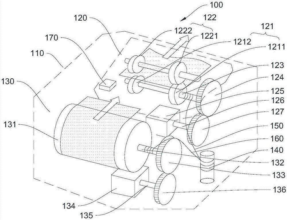
[0033] Please refer to figure 1 , the present embodiment provides a temporary banknote collection device 100, which includes a housing 110, a conveying roller portion 120, a drum portion 130, a manual wheel 140, a first traction rope 150, a second traction rope 160, an infrared sensor 170 and an alarm 180, wherein, in this embodiment, the conveying roller part 120, the drum part 130, the manual wheel 140, the first traction rope 150, the second traction rope 160, the infrared sensor 170 and the alarm 180 are all arranged in the casing 110 .

[0034] As an implementation of this embodiment, the conveying roller part 120 includes a driving roller 121, a driven roller 122, a roller shaft 123, a first gear 124, a conveying motor 125, a conveying motor shaft 126 and a second gear 127, wherein, The function of the conveying roller part 120 is to convey the banknotes put in by the user to the collection place of the temporary banknote collection device 100 , that is, to convey the b...


PUM


Abstract

The invention provides a paper currency temporary collection device and an automatic transaction device, and relates to the transaction device manufacturing field. The conveying roller part of the paper currency temporary collection device comprises a driving roller, a driven roller, a first gear, a roller shaft, a conveying motor, a second gear, and a conveying motor shaft, and the first gear is engaged with the second gear. A rotating drum part comprises a rotating drum, a third gear, a rotating drum shaft, a driving motor, a fourth gear, and a driving motor shaft, and the third gear is engaged with the fourth gear. A hand-operated wheel is connected with a first traction rope and a second traction rope. The first traction rope is connected with the roller shaft, and the second traction rope is connected with the rotating drum shaft. An infrared sensor is coupled with an alarming device, and the alarming device is used to give alarms, when inclination of paper currency conveyed between the conveying roller part and the rotating drum part is detected by the infrared sensor. The possibility of the paper jam of the paper currency during the conveying process is detected in a real-time manner, and the paper currency, which is used to transmit error information caused by the paper jam, is withdrawn by one hand, and therefore time is saved.

Description

technical field [0001] The invention relates to the field of transaction device manufacturing, in particular to a banknote temporary collection device and an automatic transaction device. Background technique [0002] Generally, in automatic cash machines and other automatic transaction devices, when banknotes are deposited, the authenticity identification and counting are carried out by the identification part, and they are temporarily collected in the temporary collection device for banknotes at the same time. Transport to banknote storage for collection. [0003] But in the prior art, in the process of temporarily collecting banknotes to the banknote temporary collection device, when an error occurs due to paper jams, the staff needs to manually rotate the operation button to withdraw the banknotes, but due to the transport in the banknote temporary collection device The roller part and the drum part are two separate parts, and one part can only be rotated with one hand,...

Claims


Application Information

Patent Timeline
IPC IPC(8): G07D11/00
CPCG07D11/0096G07D11/16G07D11/26
Inventor 陈星
Owner SHENZHEN YIHUA COMP
Why Eureka
Try Eureka