Method and system for deforming a drive rod in a door after an impact to the door

a technology a door is applied in the field of a drive rod deformation method and a system for a door after an impact to the door, which can solve the problems of permanently or semi-permanently open doors, undesirable, and inability to permanently disable the drive rod,

Active Publication Date: 2012-08-07
TOYOTA MOTOR CO LTD
View PDF65 Cites 24 Cited by
  • Summary
  • Abstract
  • Description
  • Claims
  • Application Information

AI Technical Summary

Benefits of technology

[0006]The present invention is a method and system for deforming a drive rod in a door after an impact to the door. The present invention includes an automobile having a door with a door handle, a drive rod, a latching system, a striker, and a drive rod deformation member. The drive rod deformation member can be positioned adjacent to the drive rod. Upon impact to the door, the drive rod deformation member impacts and deforms the drive rod. The deformation of the drive rod corresponds to a compression of the door. The deformation of the drive rod prevents the drive rod from controlling the latching system to disengage from the striker through compression of the door. This allows the door to remain in the closed position instead of the open position prior to actuations by the door handle. Furthermore, the present invention can allow the door to be opened by actuating the door handle, even after the drive rod is impacted by the drive rod deformation member. This can be beneficial, for example, in allowing the user of the automobile to easily exit the automobile, or for other people to access the user of the automobile.

Problems solved by technology

Having the door be left permanently or semi-permanently open is undesirable.
Furthermore, some solutions permanently disable the drive rod.
However, in such situations, the door may not be opened when the door handle is actuated.

Method used


Image

  • Method and system for deforming a drive rod in a door after an impact to the door
  • Method and system for deforming a drive rod in a door after an impact to the door
  • Method and system for deforming a drive rod in a door after an impact to the door

Examples


Embodiment Construction

[0022]Apparatus, systems and methods that implement the embodiments of the various features of the present invention will now be described with reference to the drawings. The drawings and the associated descriptions are provided to illustrate some embodiments of the present invention and not to limit the scope of the present invention. Throughout the drawings, reference numbers are re-used to indicate correspondence between referenced elements.

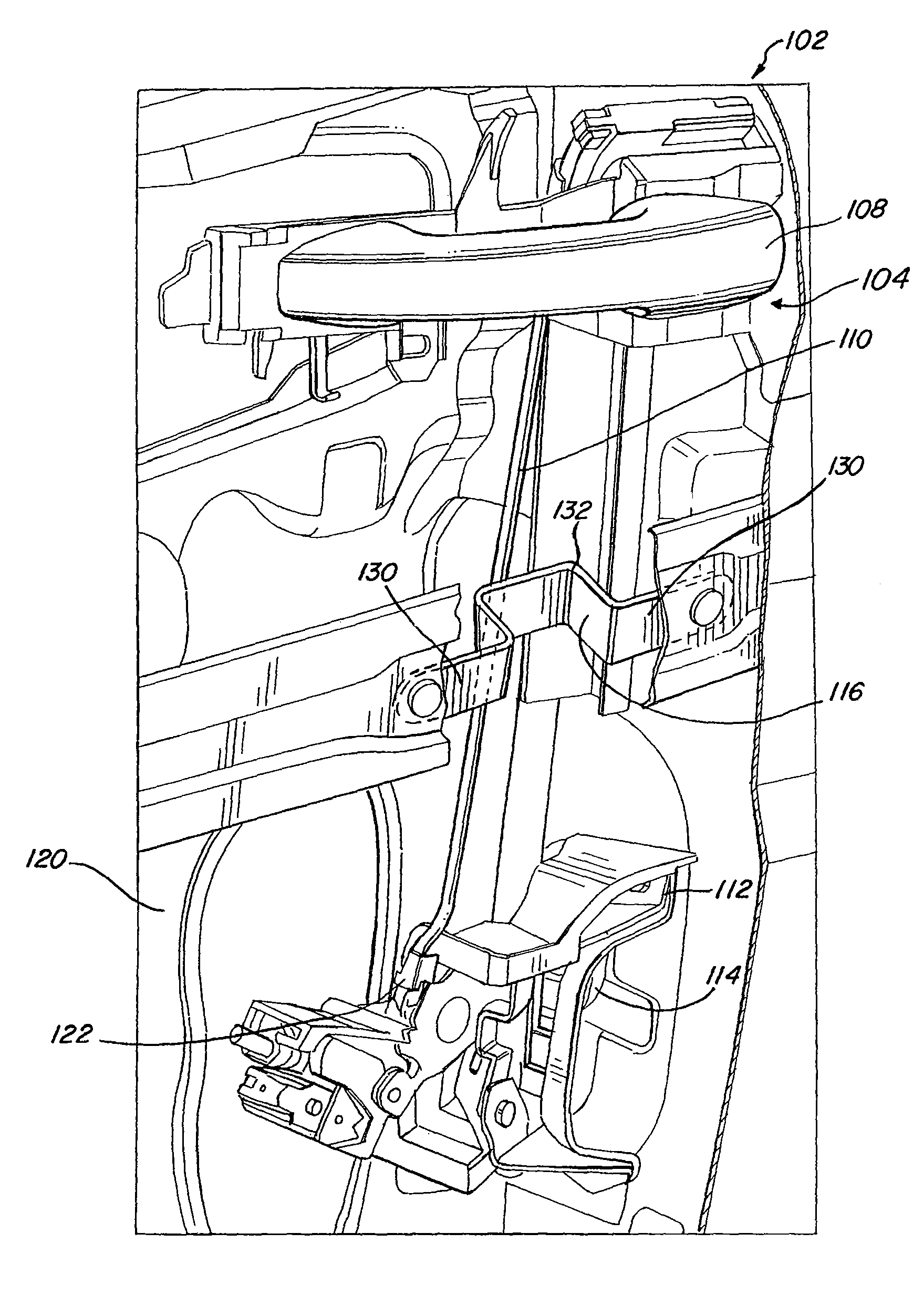
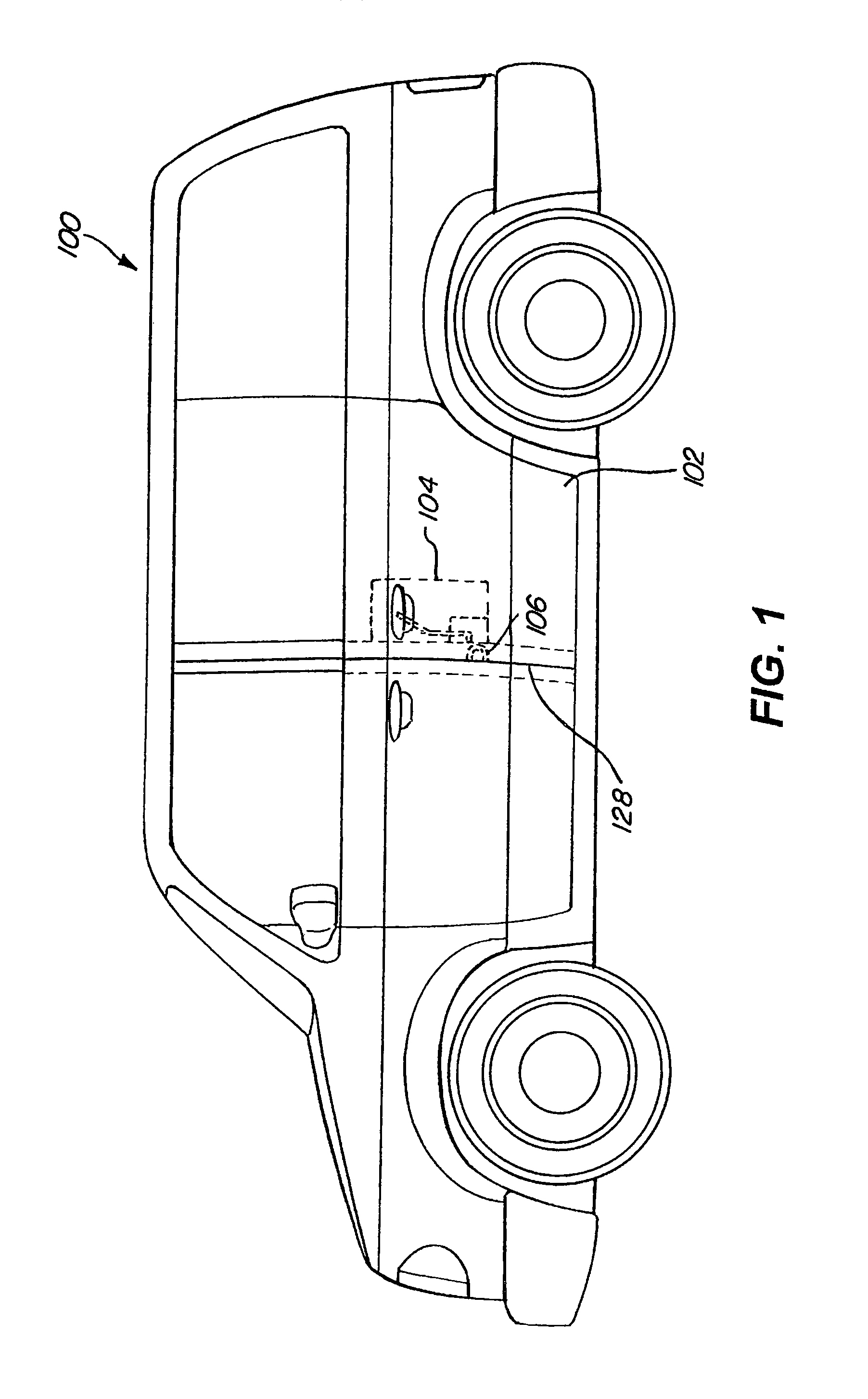
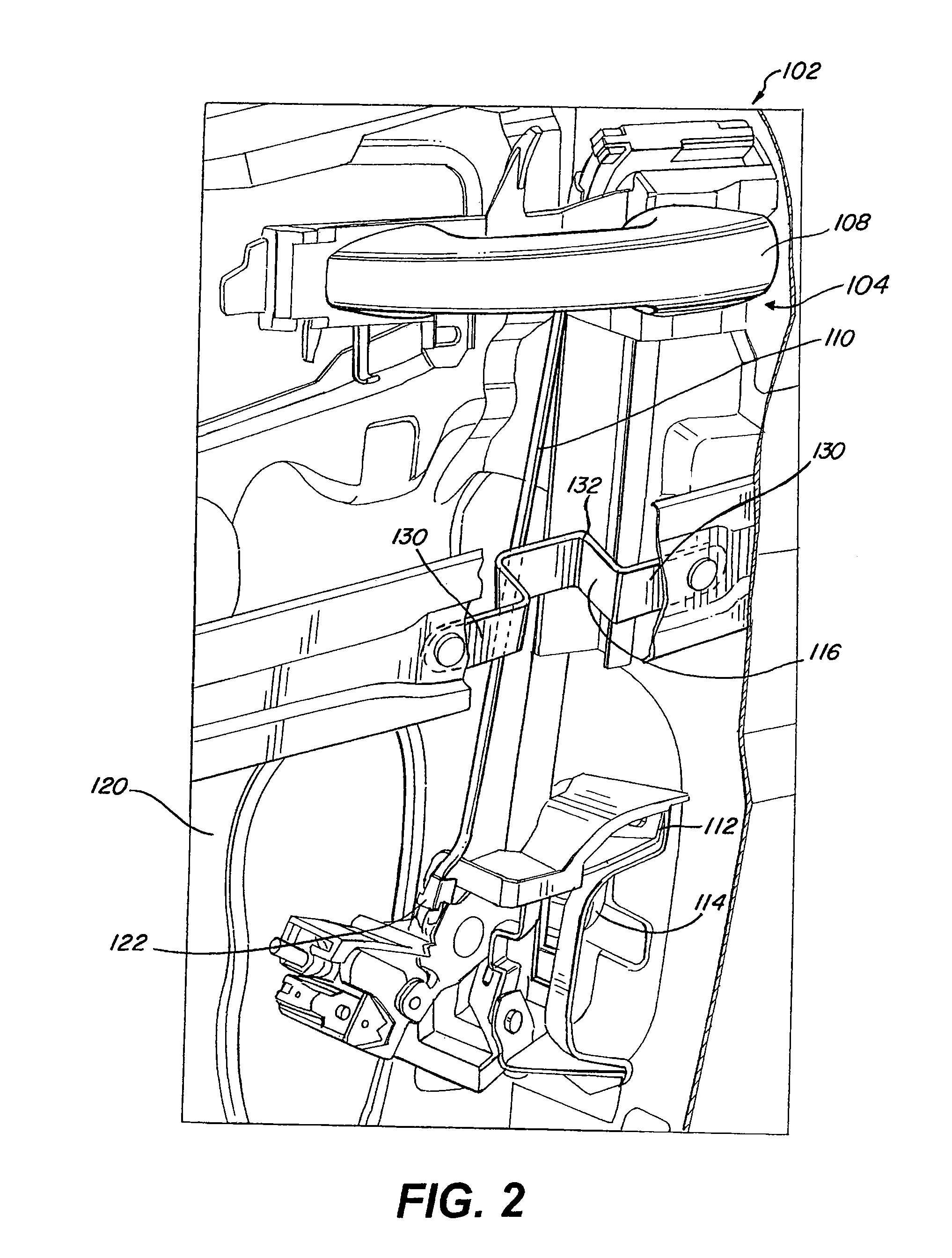
[0023]As seen in FIG. 1, a transportation device such as an automobile 100 includes a door 102, a door lock assembly 104, a striker 106, and a frame 128. The automobile 100 can be, for example, a car, a hybrid car, a car with an internal combustion engine, or any other type of vehicle which can be used to transport objects. The striker 106 is connected to the frame 128 of the automobile 100. The door 102 includes the door lock assembly 104, which is selectively engaged to the striker 106. The door 102 can be, for example, a sliding door, or a ...


PUM


Abstract

A method and system for deforming a drive rod in a door after an impact to the door. An automobile having a door with a door handle, a drive rod, a latching system, a striker, and a drive rod deformation member. The drive rod deformation member can be positioned adjacent to the drive rod. Upon impact to the door, the drive rod deformation member impacts and deforms the drive rod. The deformation of the drive rod can correspond to a compression of the door and the door can be opened by actuating the door handle. However, the deformation of the drive rod prevents the drive rod from controlling the latching system to disengage from the striker through compression of the door.

Description

BACKGROUND[0001]1. Field of the Invention[0002]The present invention relates to a method and system for deforming a drive rod in a door after an impact to the door.[0003]2. Description of the Related Art[0004]A conventional automobile includes a conventional door that opens in an outward direction. The conventional door is opened using a handle, a drive rod, a latching system, and a striker. Actuation of the handle moves the drive rod, which in turn controls the latching system to engage or disengage from the striker. During an accident where there is an impact to the door, the door can be deformed and compressed. The deformation and compression will move the latching system closer to the handle such that the drive rod permanently actuates the latching system to disengage from the striker, causing the door to be in a permanent or semi-permanent open position. Having the door be left permanently or semi-permanently open is undesirable. Furthermore, some solutions permanently disable ...

Claims


Application Information

Patent Timeline
Patent Type & Authority Patents(United States)
IPC IPC(8): E05C9/10
CPCE05B77/02E05B77/04E05B83/36Y10T292/243Y10T292/57
Inventor JORDAN, NATHANIEL P.HIGGINS, CHRISTOPHER M.RIFFE, JESSICA A.
Owner TOYOTA MOTOR CO LTD
Why Eureka
Try Eureka