Control method and control circuit of switching power supply device
A technology for controlling circuits and switching power supplies, applied in the field of power supplies, can solve problems such as increased switching loss, achieve simple circuits, and prevent discontinuous changes in input current.
- Summary
- Abstract
- Description
- Claims
- Application Information
AI Technical Summary
Problems solved by technology
Method used
Image

Examples
Embodiment 1
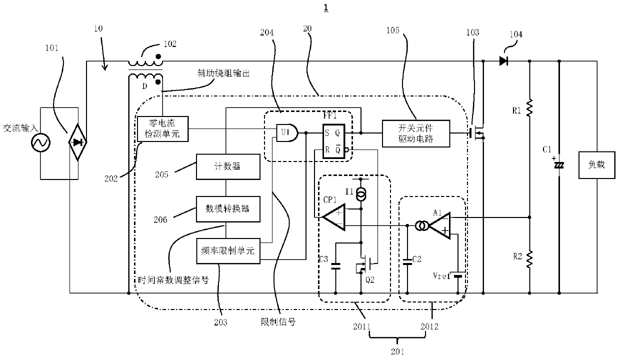
[0062] Embodiment 1 of the present application provides a control circuit for controlling on and off of switching elements in a switching power supply device, wherein the switching power supply device and the control circuit constitute a switching power supply device.
[0063] figure 1 is a circuit configuration diagram of the switching power supply device of the first embodiment. Such as figure 1 As shown, the switching power supply device 1 includes a switching power supply device 10 and a control circuit 20, wherein the switching power supply device 10 includes a rectifying unit 101, an inductor 102, a switching element 103, and a diode 104, and the control circuit 20 includes a turn-off time control unit 201 , a zero current detection unit 202 , a frequency limiting unit 203 and a conduction moment control unit 204 .
[0064] Such as figure 1 As shown, in the switching power supply device 10, the rectifying unit 101 is used to rectify the AC voltage of the input AC p...
Embodiment 2
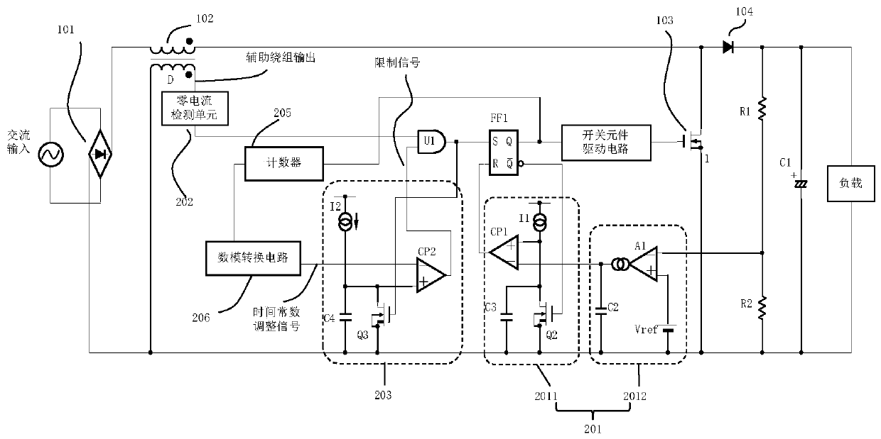
[0090] Embodiment 2 of the present application provides a control circuit, which is a specific implementation manner of the control circuit in Embodiment 1. In Embodiment 2, the structure of the frequency limiting unit 203 is described. Like the first embodiment, the control circuit and the switching power supply device of the second embodiment constitute a switching power supply device.
[0091] image 3 is the circuit structure diagram of the switching power supply device of embodiment 2, and figure 1 The same parts will not be described repeatedly. image 3 and figure 1 The difference is that image 3 The composition structure of the frequency limiting unit 203 is shown.
[0092] Such as image 3 As shown, the frequency limiting unit 203 may include a capacitor C4, a switch Q3, a comparator CP2, and a current source I2, wherein the output terminal of the comparator CP2 is used as the output terminal of the frequency limiting unit 203, and the inverting input termina...
Embodiment 3
[0110] Embodiment 3 of the present application provides a control method for a switching power supply, which corresponds to the control circuits of Embodiment 1 and Embodiment 2, and is used to control figure 1 , figure 2 and image 3 The switching elements in the switching power supply shown are controlled.
[0111] Figure 10 It is a schematic flow chart of the control method of the present embodiment 3, such as Figure 10 As shown, the method includes:
[0112] S1001. Control the disconnection of the switch element according to the voltage difference between the reference voltage and the output DC voltage;
[0113] S1002. Detect the moment when the current flowing through the inductor is zero;
[0114] S1003. Generate a limit signal according to the time constant adjustment signal, the limit signal is used to set a delay period from the moment when the switching element is turned off, wherein the magnitude of the time constant adjustment signal changes with time; and...
PUM
 Abstract
Description
Claims
Application Information
 - R&D
- Intellectual Property
- Life Sciences
- Materials
- Tech Scout
- Unparalleled Data Quality
- Higher Quality Content
- 60% Fewer Hallucinations
Browse by: Latest US Patents, China's latest patents, Technical Efficacy Thesaurus, Application Domain, Technology Topic, Popular Technical Reports.
© 2025 PatSnap. All rights reserved.Legal|Privacy policy|Modern Slavery Act Transparency Statement|Sitemap|About US| Contact US: help@patsnap.com