Receiver and assembly process thereof

A receiver and installation cavity technology, applied in the field of receivers, can solve the problem that the receiver cannot realize two different types, and achieve the effects of improving electromagnetic conversion efficiency, good quality, beautiful and saturated sound

Inactive Publication Date: 2017-09-22
SUZHOU YICHUAN TECH CO LTD
View PDF1 Cites 0 Cited by
  • Summary
  • Abstract
  • Description
  • Claims
  • Application Information

AI Technical Summary

Problems solved by technology

[0005] Therefore, the technical problem to be solved by the present invention is to overcome the problem that the receiver in the prior art cannot realize two different audio signals, and the installation of the receiver is complicated.

Method used


Image

  • Receiver and assembly process thereof
  • Receiver and assembly process thereof
  • Receiver and assembly process thereof

Examples


Embodiment 1

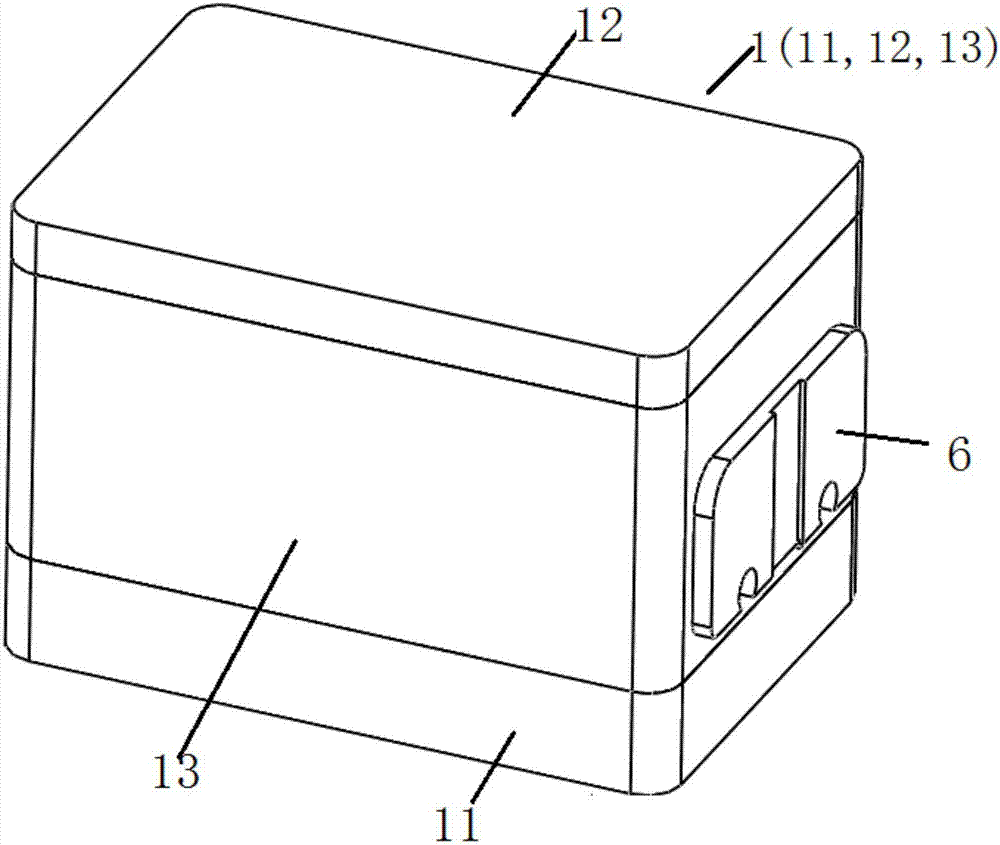
[0070] This embodiment provides a receiver, such as Figure 1 to Figure 3 As shown, it includes a housing 1 , a set of vibration mechanisms, a set of electromagnetic drive mechanisms 3 , sound pipes 5 and welding pads 6 .

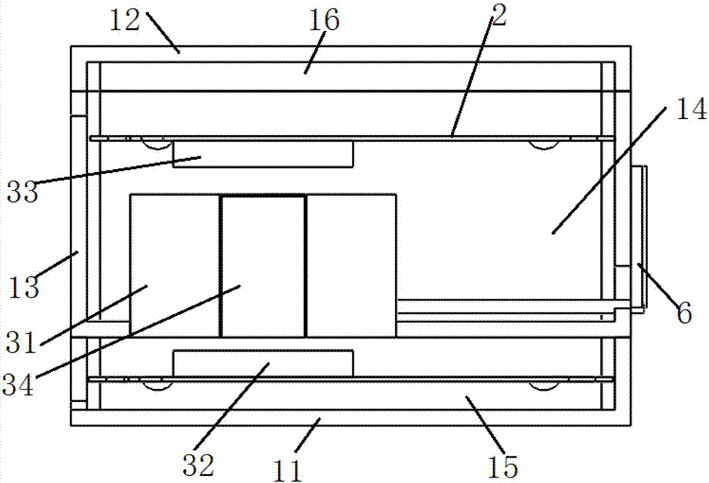
[0071] Such as figure 1 and figure 2 , the shell 1 includes a first shell 11 , a second shell 12 and a third shell 13 . The first housing 11 is composed of a first bottom surface and a side wall; the second housing 12 is composed of a second bottom surface and a side wall; the third housing 13 is composed of a third bottom surface and a side wall, and is arranged on the first housing. Between 11 and the edge of the second housing 12 , one end of the third housing 13 facing the second bottom surface is open, and the third bottom surface facing the first bottom surface is provided with an installation hole suitable for installing the coil 31 .

[0072] Such as figure 2 As shown, the vibration mechanism includes two diaphragm mechanisms 2 arranged in par...

Embodiment 2

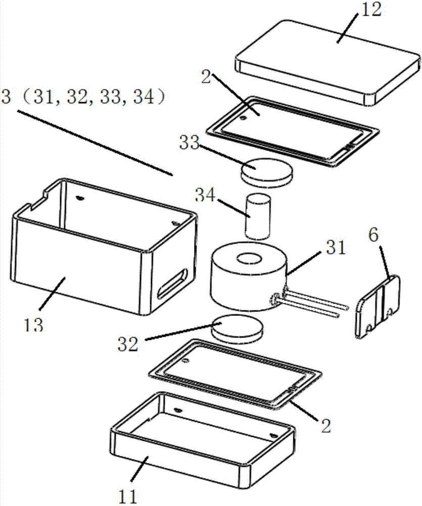
[0105] This embodiment provides an assembly process of a receiver, which includes a first housing 11, a second housing 12, a third housing 13, a coil 31, a first magnet 32, a second magnet 33, and two diaphragm mechanisms 2 and the magnetization component 34. The assembly process of the receiver comprises the following steps:

[0106] S1: Fix the first magnet 32 ​​on the side surface of the reed 21 in the first diaphragm mechanism 2 facing away from the sound diaphragm 23, and then install the first diaphragm mechanism 2 on the inner wall surface of the first housing 11 , the sound membrane 23 faces the side of the first bottom surface of the first casing 11 to form a first module;

[0107] S2: Install the magnetization component 34 in the inner cavity of the coil 31 in advance, and install the coil 31 on the installation hole of the third housing 13;

[0108] The second magnet 33 is fixed on the side surface of the reed 21 facing away from the sound membrane 23 in the diaph...


PUM

PropertyMeasurementUnit
Caliberaaaaaaaaaa

Abstract

The invention discloses a receiver and its assembly process. The receiver includes a shell, a vibrating mechanism and an electromagnetic drive mechanism. Each set of vibrating mechanisms includes two diaphragm mechanisms arranged in parallel in the inner cavity of the shell, which divides the inner cavity of the shell into a first The sounding cavity, the second sounding cavity and the installation cavity; the electromagnetic drive mechanism is used to simultaneously drive the suspended ends on the reeds of the two diaphragm mechanisms in a group of vibration mechanisms to reciprocate in opposite vibration directions. The assembly process includes fixing the first magnet to a diaphragm mechanism, fixing the diaphragm structure in the first casing; fixing the second magnet to another diaphragm mechanism, fixing the diaphragm mechanism in the second casing, Then fix the second shell and the first shell. Different audio signals are formed in the two sounding chambers, and the two different audio signals are mixed again. A set of electromagnetic drive mechanism simultaneously drives the two diaphragm mechanisms to do opposite reciprocating vibrations, so that the receiver emits different audio signals.

Description

technical field [0001] The invention relates to the technical field of receivers, in particular to a receiver and an assembly process thereof. Background technique [0002] The receiver is an electroacoustic device that converts audio electrical signals into audio signals without sound leakage. It is widely used in communication terminal equipment such as mobile phones, fixed phones, and earphones to realize audio output. [0003] With the continuous development of mobile devices, the structure of the receiver is constantly updated. For example, the receiver disclosed in Chinese patent document CN103067806A integrates the reed and flapping mechanism in the traditional moving iron receiver to form a new diaphragm mechanism. Including the shell, the diaphragm mechanism installed horizontally in the inner cavity of the shell; the diaphragm mechanism includes an E-shaped reed, a coil set on the root of the E-shaped middle wall, and the other end of the reed is used as the vibrat...

Claims


Application Information

Patent Timeline
IPC IPC(8): H04R9/08H04R9/02
CPCH04R9/08H04R9/02H04R2410/00
Inventor 吴哲
Owner SUZHOU YICHUAN TECH CO LTD
Why Eureka
Try Eureka