
Planting device and combined containing grooves thereof

A combined type and tank technology, which is applied in cultivation, soilless cultivation, botany equipment and methods, etc., can solve problems such as difficult cleaning operations, inconvenient storage and transportation processes, and time-consuming

Inactive Publication Date: 2017-09-26
SHENTER ENTERPRISE
View PDF6 Cites 0 Cited by
  • Summary
  • Abstract
  • Description
  • Claims
  • Application Information

AI Technical Summary

Problems solved by technology

[0004] The planting device found that there are still some problems in the actual use experience. For example, as far as the sink structure of the planting device is concerned, it is made of a hard shell (such as stainless steel, glass, plastic). There is no problem with the function of holding water in the body-shaped water tank, but the problem lies in the cleaning process and storage and transportation processes. The general reason is that in the use of planting devices, after each or a certain number of cultivated plants are harvested, It is inevitable that bacteria will be produced in the water tank due to the formation of moss and water stains. Based on the quality of planting, the industry must carry out cleaning and disinfection of the water tank. During this process, because the hard basin-shaped shell of the water tank has many twists and turns, Therefore, the cleaning operation is quite difficult and time-consuming. From the perspective of storage and transportation, even though the hard sinks can be stacked with each other through the inclined wall shape to reduce the transportation volume, it may still be due to the excessively long bottom area and Its overall sides are hard surface-like shape and other factors, which cause inconvenience in the storage and transportation process

Method used


Image

  • Planting device and combined containing grooves thereof
  • Planting device and combined containing grooves thereof
  • Planting device and combined containing grooves thereof

Examples


Embodiment Construction

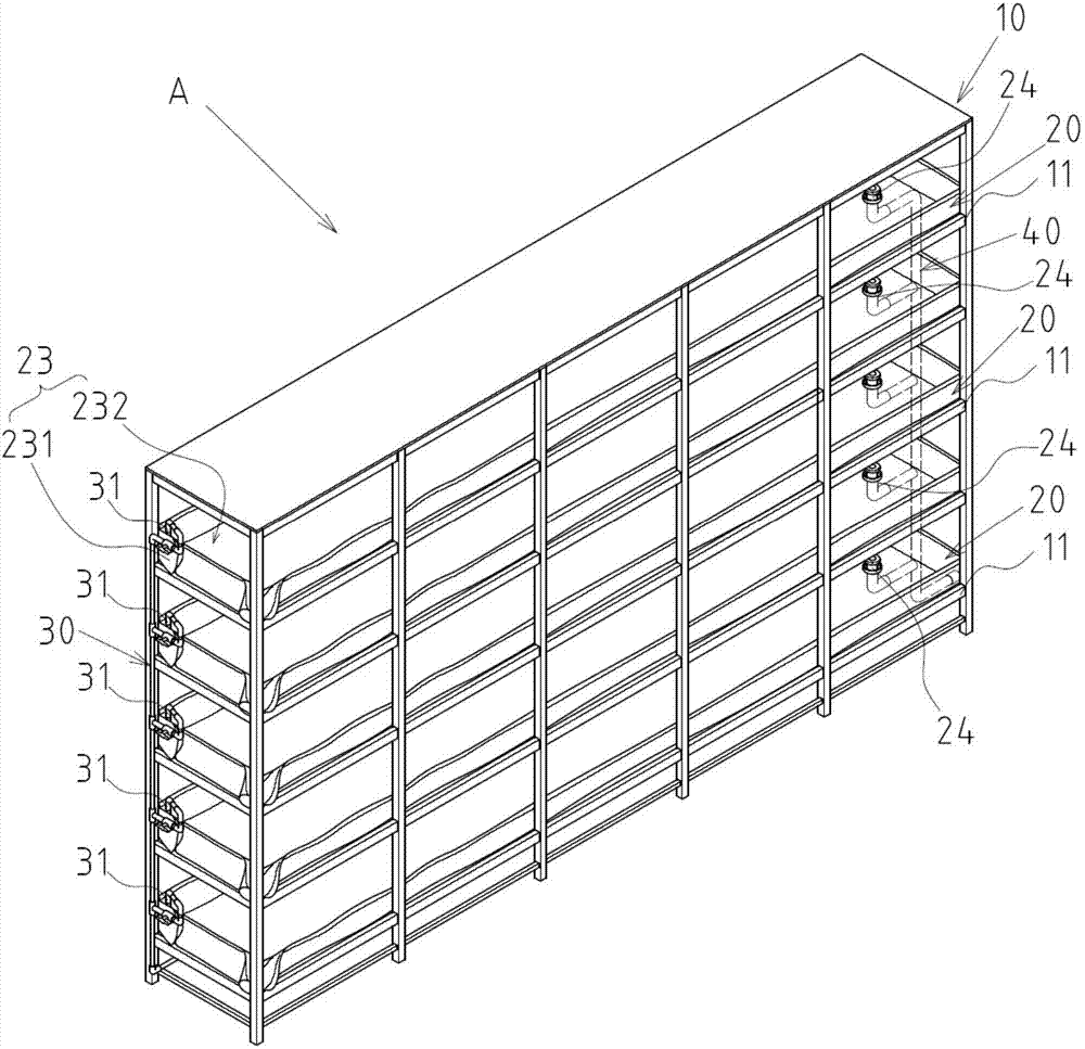
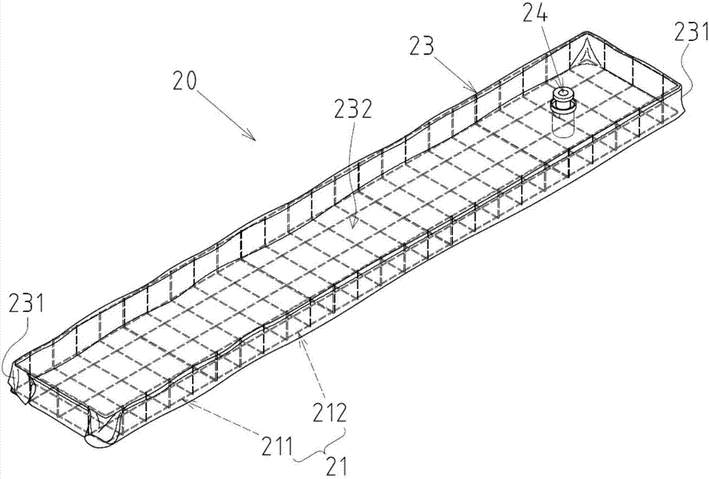
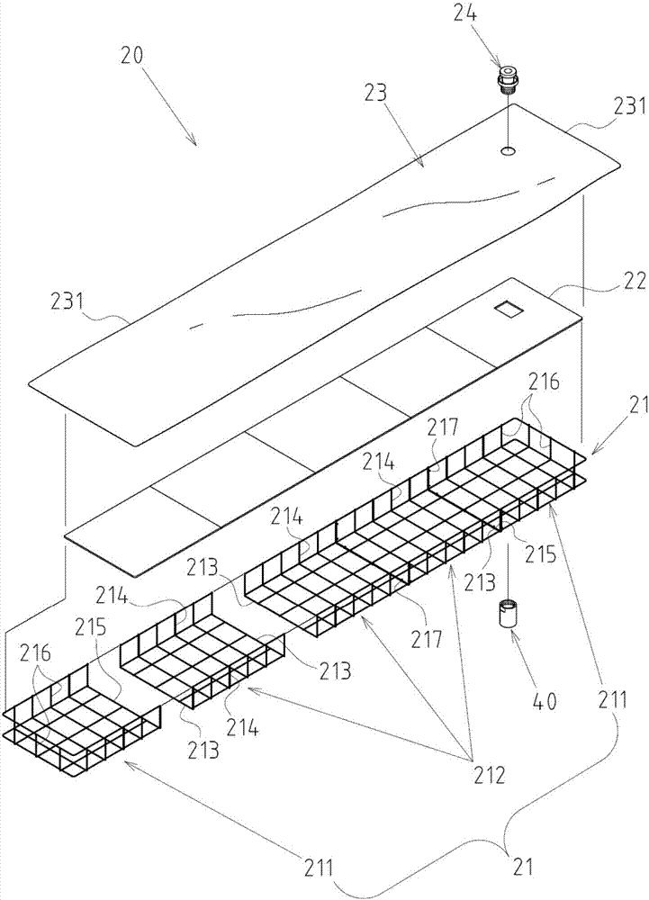
[0017] Such as figure 1 , 2 , 3, and 4 show the preferred embodiments of the planting device of the present invention and its combined container, but these embodiments are for illustration purposes only, and are not limited by this structure in patent applications; Planting device A comprises the following components:

[0018] A frame body 10 has at least one frame 11;

[0019] At least one combined container 20 is arranged on the shelf 11 of the frame body 10, and each combined container 20 includes: at least one frame 21, including two end unit frame bodies 211 and at least one intermediate unit frame that are combined and positioned with each other Body 212, wherein each middle unit frame body 212 has two sets of borders 213 and two middle section vertical side frames 214 that are open, and each end unit frame body 211 has a single group border 215 and one end that is open. The part stands toward the side frame 216, so that the assembling edge 213 of the middle unit fram...


PUM


Abstract

The invention discloses a planting device and combined containing grooves thereof. The planting device mainly comprises a frame body with a layer frame, the combined containing grooves arranged on the layer frame of the frame body, a water supply pipeline arranged and positioned on the frame body, and a drainage pipeline. Each combined containing groove comprises a frame formed by combining an end unit frame body and a middle unit frame body, a base plat arranged in the frame and a light shading waterproof fabric laid on the base plate, the peripheral region of the waterproof fabric stretches upwards in a curved mode along the middle section vertical side frame and the end vertical side frame of the frame to form a containing groove, the containing groove is provided with a water drainage portion, the water supply pipeline is provided with a water outlet end stretching into the containing groove of the combined containing groove, and the drainage pipeline is connected with water drainage portions of the combined containing grooves. Accordingly, the combined containing grooves are convenient to clean and small in storage and transfer size.

Description

technical field [0001] The invention relates to a planting device; in particular, it refers to an innovative structural form of a planting device. Background technique [0002] The planting device referred to in the present invention is a main hardware structure that is widely installed in the indoor lighting planting environment. With the current indoor planting industry being valued and flourishing, the structural design of the planting device is good and bad. Whether or not, it has relatively received the attention and attention of the relevant industries. [0003] At present, the structure of the planting device is basically the same. Most of them use the shelf structure as the main body. Water tanks are set in each shelf to hold the culture solution. Each tank is usually sealed with a board to cover the culture solution. Planting holes distributed at intervals, each planting hole is provided with a planting medium (such as sponge) to provide an implantation site for th...

Claims


Application Information

Patent Timeline
Patent Type & Authority Applications(China)
IPC IPC(8): A01G31/06
CPCA01G31/06Y02P60/21
Inventor 赖铭晓黄国书
Owner SHENTER ENTERPRISE
Learn More