Double-roller crusher

A crusher, double-roller technology, applied in the field of double-roller crushers, can solve the problem of material entering between the rollers and the wall of the frame, and achieve the effect of reducing the probability of replacement, simple installation and disassembly, and reducing maintenance costs.

Active Publication Date: 2017-09-26
ZHEJIANG BOYUAN MACHINERY EQUIP
View PDF9 Cites 1 Cited by
  • Summary
  • Abstract
  • Description
  • Claims
  • Application Information

AI Technical Summary

Problems solved by technology

This device enables the material to be crushed at the working surface end of the roller, so that the working surfac...

Method used


Image

  • Double-roller crusher
  • Double-roller crusher
  • Double-roller crusher

Examples


Embodiment 1

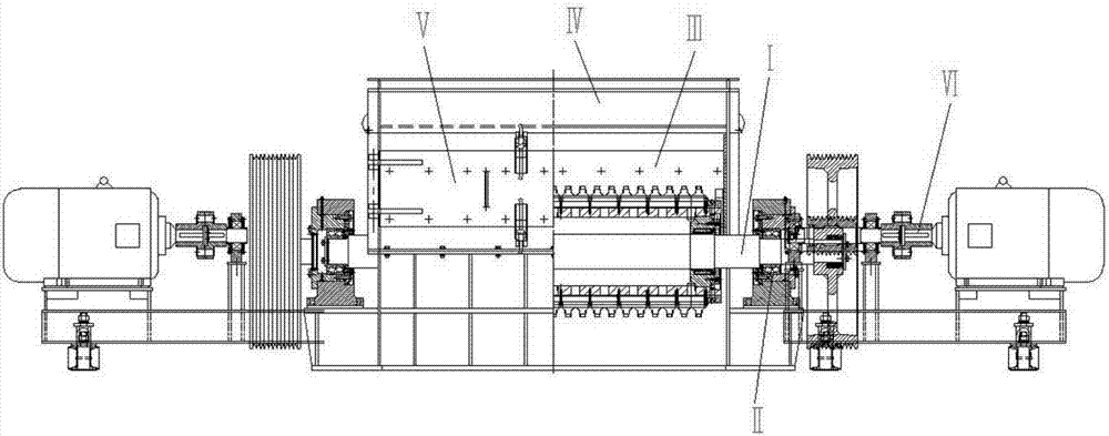
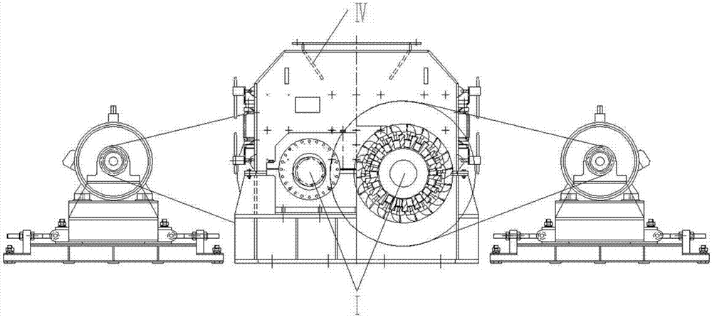
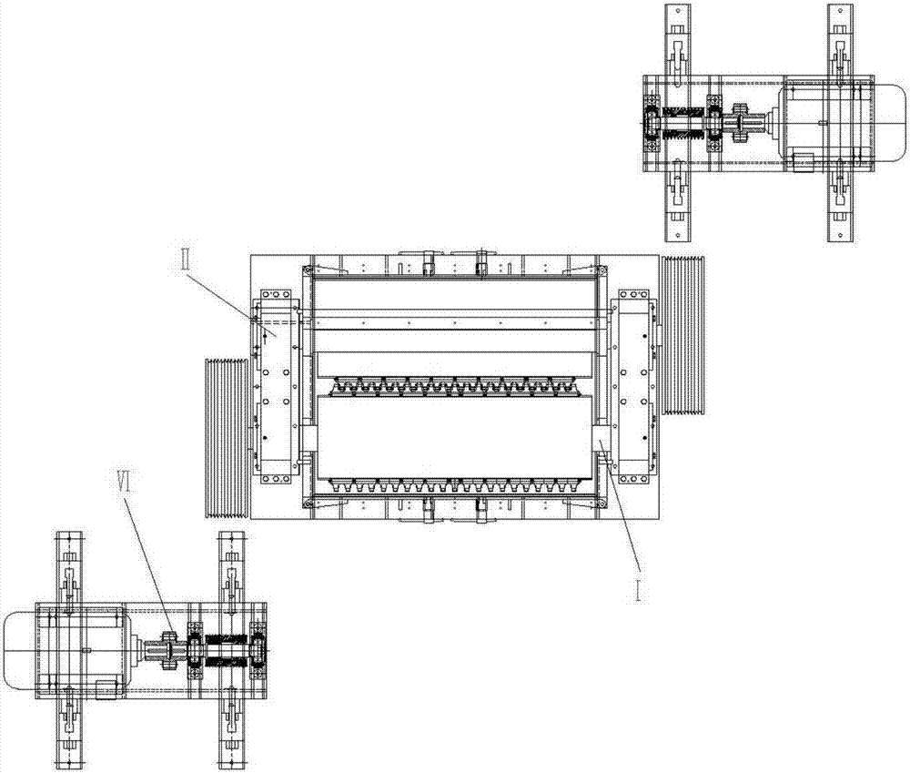
[0103] see Figure 1 to Figure 8 , Figure 12 to Figure 38 . The double-roller crusher in this embodiment includes two main shafts I, two toothed rollers, a frame with a crushing chamber, a double-roller spacing adjustment device II, a liner device III, a material guide structure IV, and a side door V. Motor protection device VI.

[0104] The main shaft I in this embodiment includes the first shaft body I1, the second shaft body I2, the third shaft body I3, the fourth shaft body I4, the fifth shaft body I5, the sixth shaft body I6, The seventh axis body I7, the eighth axis body I8 and the ninth axis body I9. The sides of the nine shafts in this embodiment are not provided with mounting holes and / or keyways, and the mounting holes include screw holes, through holes, special-shaped holes, etc.; the first shaft I1 in this embodiment is connected to the No. 1 bearing II1 , the seventh shaft I7 is connected in the second bearing II7. The third shaft body I3, the fourth shaft b...

Embodiment 2

[0134] see Figure 1 to Figure 5 , Figure 9-Figure 12 . The double-roller crusher in this embodiment includes two main shafts I, two toothed rollers, a frame with a crushing chamber, a double-roller spacing adjustment device II, a liner device III, a material guide structure IV, and a side door V. Motor protection device VI.

[0135] The toothed roller in this embodiment is suitable for fine crushing, and includes a roller and a plurality of toothed plates 2 . The roll includes a roll body 1 . The tooth plate 2 is fixed on the surface of the roller body 1 . The surface of the roller body 1 is provided with several tooth installation grooves 11 along the axial direction of the roller body 1 (direction of the central axis 14). The positioning hole 12 of positioning, the shape of the positioning hole 12 is a cone shape, the diameter of the upper opening of the positioning hole 12 is greater than the diameter of the lower opening of the positioning hole 12, and the upper ope...


PUM


Abstract

The invention relates to a double-roller crusher. The double-roller crusher comprises rollers and a plurality of toothed plates. Each roller comprises a roller body. The toothed plates are fixed to the surfaces of the roller bodies. Each toothed plate comprises a positioning column, a plate seat and a tooth, wherein the positioning column is fixedly connected with the bottom of the plate seat and is in a circular truncated cone shape, and the diameter of the upper bottom face of the positioning column is larger than the diameter of the lower bottom face of the positioning column. A plurality of tooth installation grooves are formed in the surface of each roller body in the axial direction of the roller body, the bottom of each tooth installation groove is provided with a plurality of positioning holes used for positioning the corresponding tooth in the radial direction of the roller body, each positioning hole is in a circular truncated cone shape, the diameter of an upper opening of each positioning hole is larger than the diameter of a lower opening of the positioning hole, the upper openings of the positioning holes are formed in the bottoms of the tooth installation grooves, and the bottoms of the tooth installation grooves are further provided with a plurality of connection holes. The positioning columns are installed in the positioning holes. Fastener holes are matched with the connection holes. The double-roller crusher is reasonable in structural design, firm, reliable in performance and long in service life.

Description

technical field [0001] The invention relates to a double-roll crusher, which belongs to the field of crushers. Background technique [0002] The toothed rollers in the existing double-roller crusher are worn out during long-term use, resulting in high maintenance costs and maintenance time. The production cycle of the toothed rollers is about 10 to 20 days. Therefore, a double-roller crusher The production cycle is about one month. And once the toothed roller wears out, it is necessary to replace the roller body, which brings greater economic loss. [0003] Chinese patent 201410353652.3 discloses a toothed roller for a plug-in tooth crusher with an interlocking mechanism and a pressing shear blade, which includes a plurality of hollow roller bodies, and multiple rows of tooth handles are respectively arranged on the outer circular surfaces of the plurality of hollow roller bodies A plurality of roller teeth are respectively inserted in the holes of the multi-row tooth shan...

Claims


Application Information

Patent Timeline
IPC IPC(8): B02C4/08B02C4/28B02C4/30B02C4/32B02C4/42B02C23/04
CPCB02C4/08B02C4/28B02C4/30B02C4/32B02C4/42B02C23/04
Inventor 陈一佳陈斌嘉陈飞马为良
Owner ZHEJIANG BOYUAN MACHINERY EQUIP
Why Eureka
Try Eureka