Upper valve body with pressure relief compensation function and pneumatic valve using same

A valve body and pressure relief technology, which is applied in the direction of control valves, air release valves, brakes, brake components, etc., can solve problems such as failure to achieve, no compensation to improve the braking capacity, and unsatisfactory adjustment function of the space adjustment block.

Pending Publication Date: 2017-09-26
谢洪川
View PDF0 Cites 2 Cited by
  • Summary
  • Abstract
  • Description
  • Claims
  • Application Information

AI Technical Summary

Problems solved by technology

[0003] The cavity space of the valve body on the existing pneumatic valve is fixed and cannot be adjusted. After the pedaling force reaches the maximum during the braking process, the air pressure in the cavity of the pneumatic valve will not exceed the peak value, and there is no compensation for the improvement of the braking capacity. Therefore, the current The braking ability of the pneumatic valve cannot cope with a more severe working environment, and cannot achieve a better braking effect in the face of emergencies
[0004] Some pneumatic valves are set so that the chamber space can be partially adjusted. This kind of pneumatic valve controls the return of the space adjustment block through springs, etc., but this return method is subject to great resistance from the air pressure inside the chamber, and it is difficult for the space adjustment block to return to the initial position. position, so the adjustment function of this space adjustment block is not ideal

Method used


Image

  • Upper valve body with pressure relief compensation function and pneumatic valve using same
  • Upper valve body with pressure relief compensation function and pneumatic valve using same
  • Upper valve body with pressure relief compensation function and pneumatic valve using same

Examples


Embodiment 1

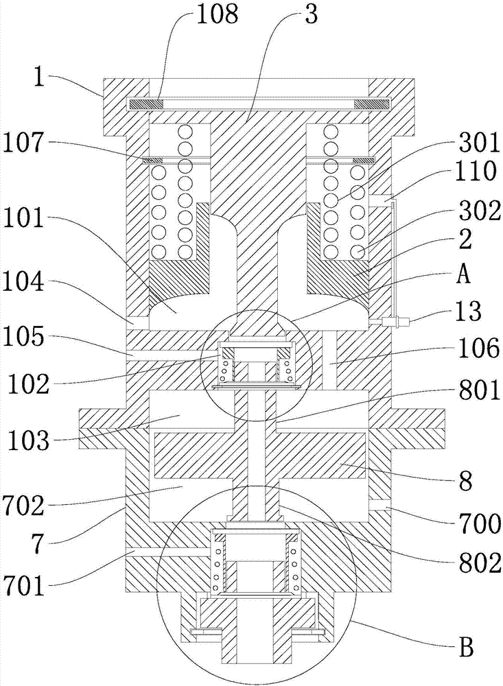
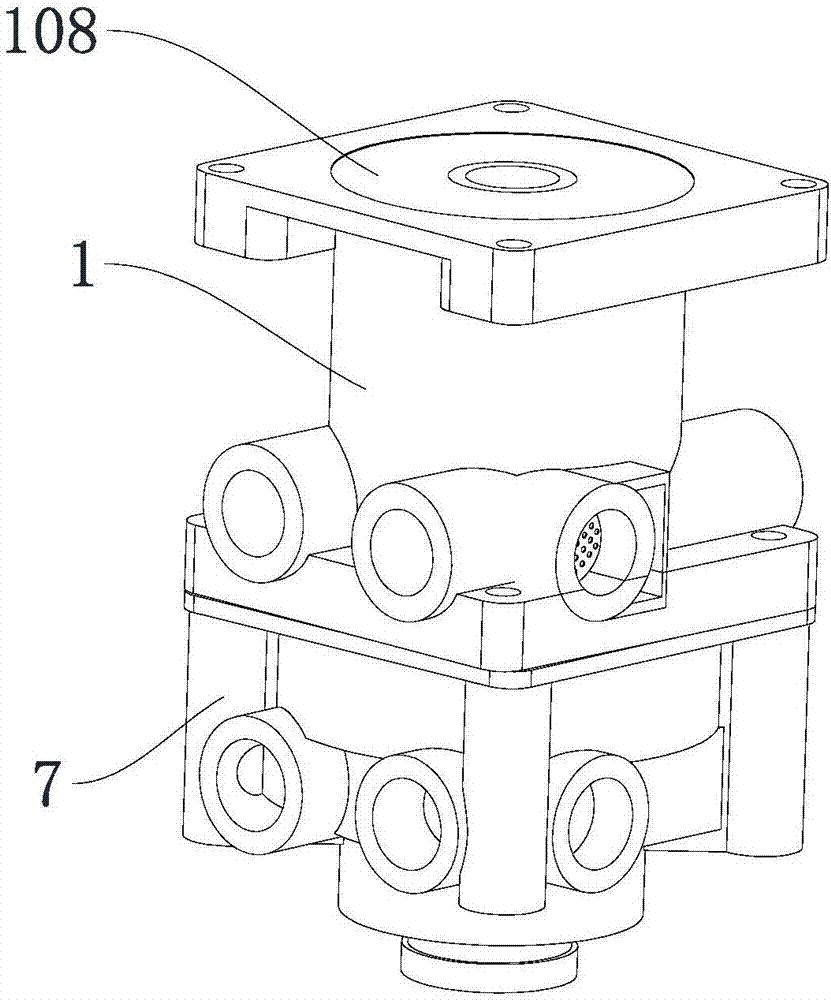
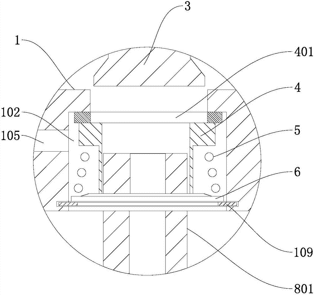
[0077] Such as figure 1 , figure 2As shown, this embodiment discloses an upper valve body with pressure relief compensation, including an upper housing 1, the upper housing 1 is provided with a connected upper chamber 101 and an upper valve gas storage chamber 102, and an upper valve Pneumatic chamber 103; the upper chamber 101 is provided with a valve core, and the upper valve chamber 102 is provided with an upper valve chamber seal 4, an upper valve gasket 401 located on the upper part of the upper valve chamber seal 4, and is sleeved in the chamber The upper valve gasket 6 on the seal, the upper valve spring 5 placed between the chamber seal and the upper valve gasket 6, the upper valve stopper 109 placed under the upper valve gasket 6, the upper valve pneumatic cavity 103 is located in the upper shell Bottom of body 1.

[0078] Preferably, both the upper chamber 101 and the upper valve air storage chamber 102 are cylindrical chambers, and the valve core is cylindrical i...

Embodiment 2

[0127] This embodiment discloses a pneumatic valve. The components and connection methods of the pneumatic valve in this embodiment are the same as those in Embodiment 1, the difference lies in:

[0128] In this embodiment, the upper valve body adopts a valve core and a compensation adjustment device with different structures.

[0129] Such as Figure 5 , Figure 6 As shown, for the spool in this embodiment, the piston sleeve 2 is a sleeve with a "mountain" shape in the longitudinal section, and the piston sleeve 2 is fixedly connected with the upper chamber 101; the inside of the piston sleeve 2 forms a second cavity with the driving piston 3 , the second cavity is provided with a return spring 301, the upper end of the return spring 301 is connected to the upper section of the driving piston 3 and the lower end is connected to the piston sleeve 2; the outer wall of the piston sleeve 2 and the inner wall of the upper housing 1 form a third cavity with a closed upper end and ...

Embodiment 3

[0136] This embodiment discloses a pneumatic valve. The components and connection methods of the pneumatic valve in this embodiment are the same as those in Embodiment 1, the difference lies in:

[0137] In this embodiment, valve cores with different structures are used for the upper valve body, and compensation adjustment devices 13 with different connection modes are used.

[0138] Such as Figure 9 , Figure 10 As shown, the spool in this embodiment, the piston sleeve 2 is a sleeve with a "mountain" shape in the longitudinal section, the piston sleeve 2 is slidably connected with the upper chamber 101, and the inside of the piston sleeve 2 forms a second cavity with the driving piston 3 , the second cavity is provided with a return spring 301, the upper end of the return spring 301 is connected to the upper section of the driving piston 3 and the lower end is connected to the piston sleeve 2; the outer wall of the piston sleeve 2 is provided with a fourth cavity with a clo...


PUM


Abstract

The invention discloses an upper valve body with a pressure relief compensation function and a pneumatic valve using the same. The upper valve body comprises an upper casing. A valve core, an upper valve chamber sealing part, an upper valve washer, an upper valve spring and an upper valve blocking part are disposed in the casing. A movable piston sleeve is arranged in the valve core. The piston sleeve can move up and down in the upper valve core to change an air storage space inside the upper casing. The pneumatic valve further comprises a lower valve body. A linkage piston, a lower valve chamber sealing part, a lower valve washer, a lower valve spring and a lower valve plug are arranged in the lower valve body. The upper valve body and the lower valve body are connected with an independent air supply pump. The lower valve body is further connected to a brake chamber. Through combined motions of the upper valve body and the lower valve, opening and closing of a gas circuit are changed, and air flow entering the brake chamber is controlled to implement automobile braking. The novel valve core is adopted, and a more efficient and more stable braking effect can be achieved.

Description

technical field [0001] The invention relates to the field of automobile brake pneumatic valves, in particular to an upper valve body with pressure relief compensation and a pneumatic valve using the upper valve body. Background technique [0002] The pneumatic valve is the main control device in the vehicle braking system. It realizes sensitive follow-up control during the braking process and release process of the dual-circuit main braking system. The brake valve is mainly composed of the upper cavity piston, the lower cavity piston, the push Rod, balance spring, return spring (upper and lower cavity), upper cavity valve, lower cavity valve, air inlet, air outlet, exhaust port, vent hole. When the driver steps on the pedal, the piston presses down the balance spring by stretching the pull rod, and the piston moves down. First, the exhaust valve is closed and the intake valve is opened. The air chamber pushes the diaphragm of the air chamber to rotate the brake cam to achie...

Claims


Application Information

Patent Timeline
IPC IPC(8): B60T15/36
CPCB60T15/36
Inventor 谢洪川
Owner 谢洪川
Why Eureka
Try Eureka