
Independent isolated flushing system with double-end-surface mechanical seal for centrifugal pump

A technology of mechanical seals and flushing systems, applied to mechanical equipment, parts of pumping devices for elastic fluids, pumps, etc., can solve problems such as high risk, prone to major safety accidents, short service life, etc., and achieve impact low effect

Inactive Publication Date: 2017-09-26
温刚
View PDF0 Cites 3 Cited by
  • Summary
  • Abstract
  • Description
  • Claims
  • Application Information

AI Technical Summary

Problems solved by technology

[0003] 1. When the conveyed medium is flammable and explosive medium, the heat generated at the mechanical seal is not cooled in time, which is extremely dangerous, has huge potential safety hazards, and is prone to major safety accidents
[0004] 2. When the working conditions are harsh, such as when there is no medium running, the medium is dry or frozen, the mechanical seal will dry out rapidly, be damaged quickly, and leak quickly
[0005] 3. When transporting high specific gravity medium, such as high specific gravity drilling fluid, the drilling fluid will stay and stick to the mechanical seal, which is extremely unfavorable to the heat dissipation of the mechanical seal, and the mechanical seal is prone to leakage
[0006] 4. The reliability of the mechanical seal is low, the service life is short, and leakage occurs in a very short time, and the service life does not meet the requirements of the industry

Method used


Image

  • Independent isolated flushing system with double-end-surface mechanical seal for centrifugal pump
  • Independent isolated flushing system with double-end-surface mechanical seal for centrifugal pump
  • Independent isolated flushing system with double-end-surface mechanical seal for centrifugal pump

Examples


Embodiment Construction

[0040] Below in conjunction with accompanying drawing and specific embodiment, the present invention will be further described

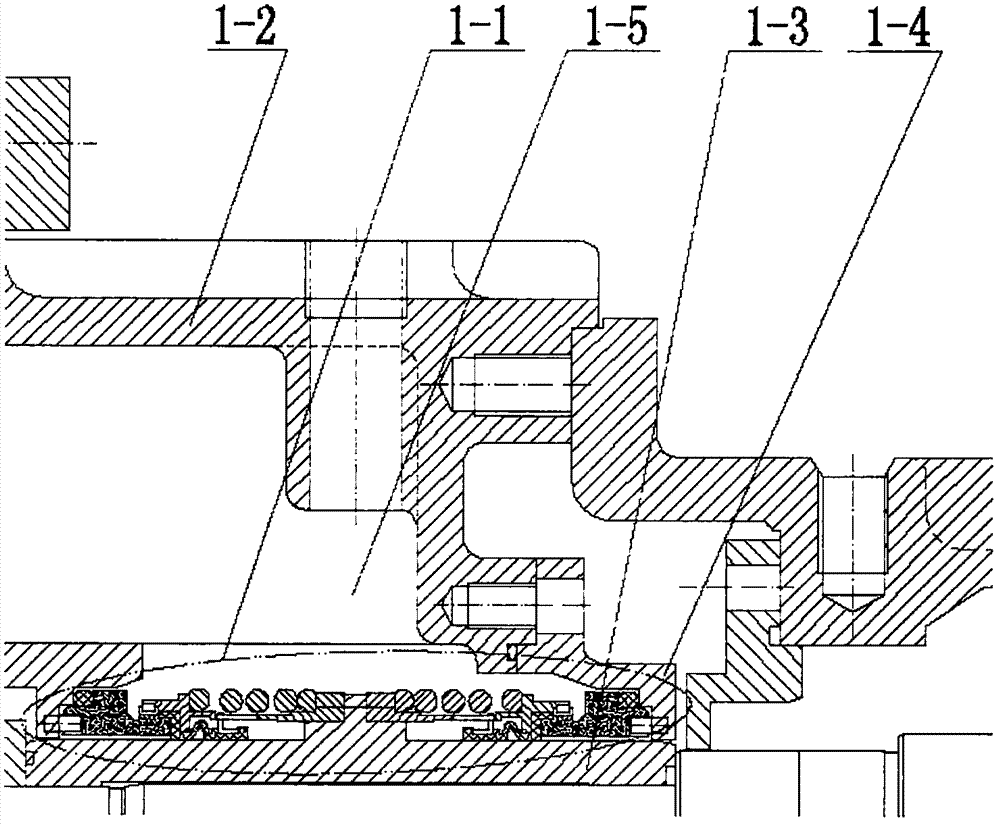
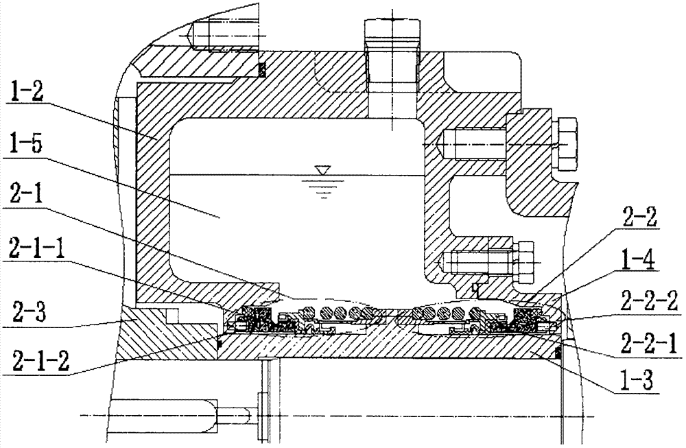
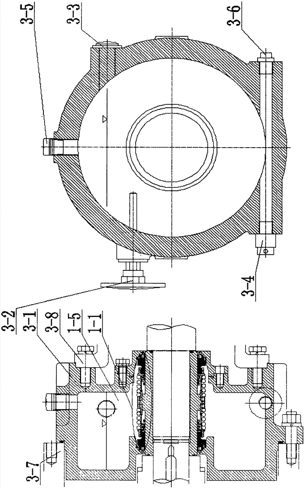
[0041] figure 1 Middle: The independent isolation and flushing system of the double-end mechanical seal for the centrifugal pump of plan 1, including the double-end mechanical seal 1-1, the isolation cavity assembly 1-2, the shaft sleeve 1-3 and the sealing gland 1-4, and the double-end mechanical seal The mechanical seal 1-1 is installed between the isolation cavity assembly 1-2 and the sealing gland 1-4, and is fixed on the shaft sleeve 1-3, and the spacer fluid 1-5 is filled between the three, and the double-end mechanical seal 1-1. Isolation chamber assembly 1-2, shaft sleeve 1-3 and sealing gland 1-4 can be assembled into a set of wearing parts, as a cartridge mechanical seal, without any adjustment, integral installation, convenient replace.

[0042] figure 2 Middle: The double-end mechanical seal 1-1 of plan 1 includes the first-level mech...


PUM


Abstract

The purpose of the present invention is to provide an independent isolation and flushing system of double-end mechanical seals for centrifugal pumps, to overcome various defects and disadvantages of centrifugal pump mechanical seals during use, to improve the stability of mechanical seal operation, and to increase the resistance to harsh conditions. The adaptability to the working conditions prolongs the service life and meets the requirements of use. In order to achieve the above purpose, an independent isolation and flushing system for a double-end mechanical seal for a centrifugal pump is provided, which is characterized in that it includes a double-end mechanical seal, an isolation cavity assembly, a shaft sleeve and a sealing gland. In order to achieve the above purpose, it is also possible to provide an independent isolation and flushing system for double-end mechanical seals for centrifugal pumps, which is characterized in that it includes double-end mechanical seals, pumping structures, seal boxes, shaft sleeves, sealing glands and liquid storage tanks Assembly, liquid storage tank assembly is filled with spacer fluid for circulating lubrication and cooling. Above-mentioned two kinds of schemes can be implemented independently, reach the object of the invention independently, embody beneficial effect.

Description

technical field [0001] The invention belongs to the flushing system of the centrifugal pump mechanical seal used in the fields of petroleum exploration, petroleum exploitation, petroleum refining and petroleum product transportation, in particular to the flushing system of the centrifugal pump mechanical seal used in drilling fluid solid control equipment in the petroleum drilling and exploration industry. Background technique [0002] At present, in the oil drilling and exploration industry, the mechanical seal of the centrifugal pump used in the drilling fluid solid control equipment does not have any flushing system, so there are many defects in the use of the mechanical seal: [0003] 1. When the conveyed medium is flammable and explosive medium, the heat generated at the mechanical seal is not cooled in time, which is extremely dangerous, poses a huge safety hazard, and is prone to major safety accidents. [0004] 2. When the working conditions are harsh, such as when t...

Claims


Application Information

Patent Timeline
Patent Type & Authority Applications(China)
IPC IPC(8): F04D29/10F04D29/58F04D29/06
CPCF04D29/106F04D29/061F04D29/588
Inventor 温刚
Owner 温刚
Learn More