Flexible display and formation method thereof

A flexible display and flexible substrate technology, applied in the direction of electric solid-state devices, semiconductor devices, climate sustainability, etc., can solve the problems of non-stretch resistance and weak tensile resistance

Active Publication Date: 2017-09-26
SHANGHAI TIANMA MICRO ELECTRONICS CO LTD
View PDF3 Cites 9 Cited by
  • Summary
  • Abstract
  • Description
  • Claims
  • Application Information

AI Technical Summary

Problems solved by technology

One of the current problems with flexible displays with two opposite bending directions is meeting or exceeding bending requirements in one bending direction, such as strong resistance to compression, but not in the other bending direction Bending requirements, such as having weak tensile resistance, that is, there is a problem of "compressive but not tensile"
At present, in the structural design of flexible displays, by setting the TFT at the neutral plane, the tension and pressure on the TFT during bending can be reduced, thereby improving the tensile and compression resistance of the TFT film layer, thereby improving The bending ability of flexible displays in different bending directions, but this design still has disadvantages: first, TFT is still a thick structure, and it will still be subjected to certain bending force, such as pulling force when bending; secondly, In a flexible display, there may be a film layer with poorer bending ability than TFT, such as stretch resistance, so that it is necessary to set the neutral plane away from the film layer of TFT

Method used


Image

  • Flexible display and formation method thereof
  • Flexible display and formation method thereof
  • Flexible display and formation method thereof

Examples


Embodiment Construction

[0142] Certain terms are used, for example, in the description and claims to refer to particular components. Those skilled in the art should understand that hardware manufacturers may use different terms to refer to the same component. The specification and claims do not use the difference in name as a way to distinguish components, but use the difference in function of components as a criterion for distinguishing. As mentioned throughout the specification and claims, "comprising" is an open term, so it should be interpreted as "including but not limited to". "Approximately" means that within an acceptable error range, those skilled in the art can solve the technical problem within a certain error range and basically achieve the technical effect. In addition, the term "coupled" herein includes any direct and indirect electrical coupling means. Therefore, if it is described that a first device is coupled to a second device, it means that the first device may be directly elect...


PUM


Abstract

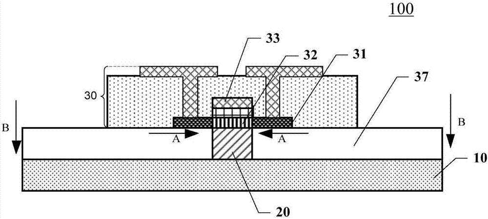
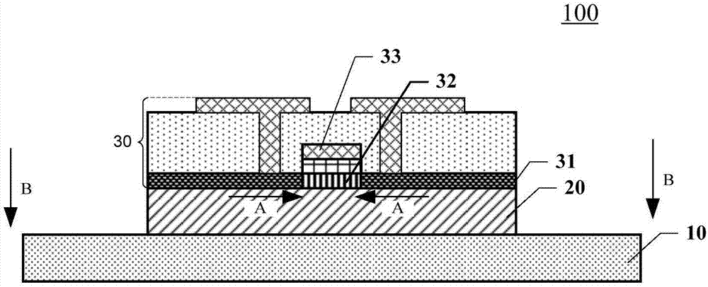
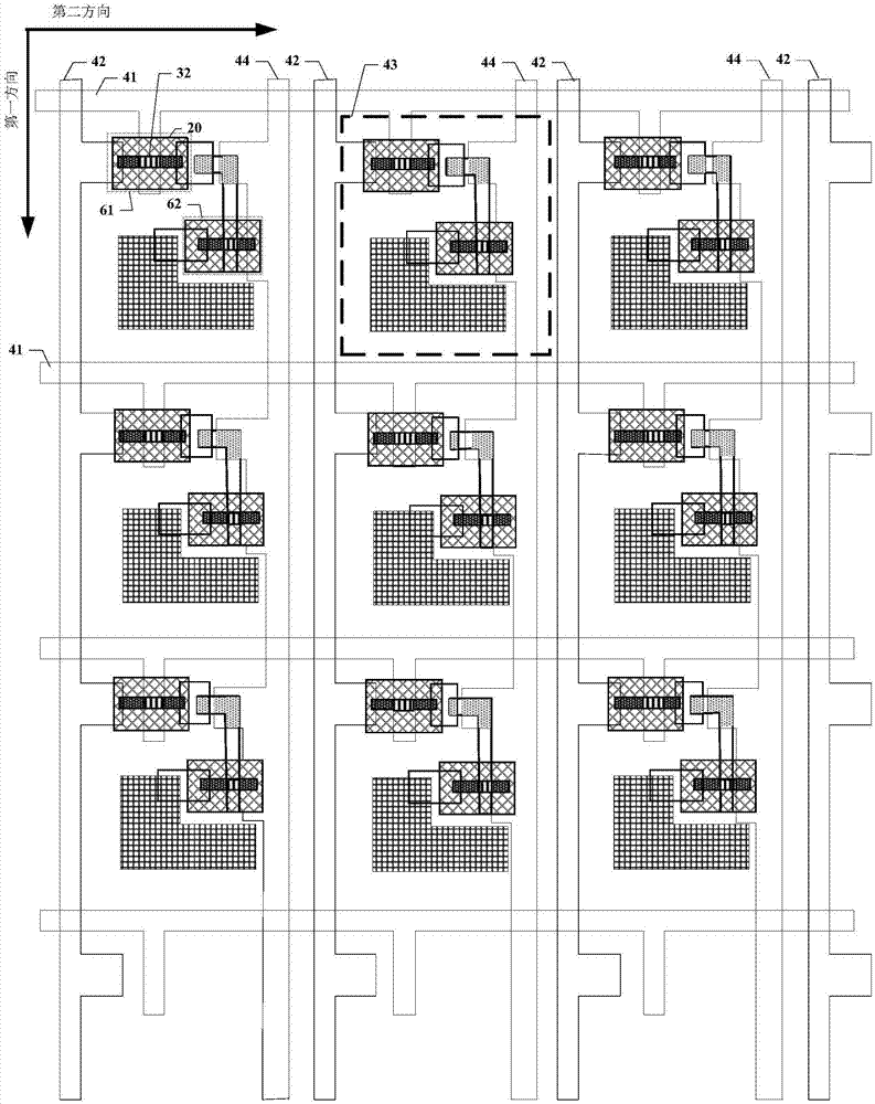
The present invention discloses a flexible display and a formation method thereof, and relates to the display technology field. The flexible display comprises a first flexible substrate; a film transistor comprising an active layer located at the first side of the first flexible substrate; and a plurality of second flexible substrates located between the active layer and the first flexible substrate. The active layer comprises a channel region, the orthographic projections of the second flexible substrates at a plane where the first flexible substrate is located at least cover the orthographic projection of the channel region at the plane where the first flexible substrate is located; and the coefficient of thermal expansion of the first flexible substrate is smaller than the coefficient of thermal expansion of the second flexible substrates. The lower portion of the active layer of the film transistor is overlapped and provided with the second flexible substrates and the first flexible substrate in order, and the coefficient of thermal expansion of the first flexible substrate is smaller than the coefficient of thermal expansion of the second flexible substrates to allow the film transistor in a flexible display to have a certain compression in the no-bending state so as to be equal to improvement of the tensile capacity of the device and facilitate improving the anti-bending capacity of the flexible display.

Description

technical field [0001] The present application relates to the field of display technology, in particular, to a flexible display and a forming method thereof. Background technique [0002] A flexible display is a foldable or bendable display device made on a flexible carrier (also called a flexible substrate). It uses a flexible substrate material as the carrier substrate of the device. ), the display components and the packaging layer all have a certain bending radius, so as to achieve full flexibility. Due to the characteristics of thin, light, portable, strong impact resistance, and aesthetic design of flexible displays, more and more people pay more and more attention to the research and innovation of flexible displays. [0003] Usually, when a flexible display is bent, multiple functional layers including TFT will be subjected to different degrees of tension or pressure. For example, the ability of the TFT film layer to withstand compression is higher than the ability t...

Claims


Application Information

Patent Timeline
Patent Type & Authority Applications(China)
IPC IPC(8): H01L27/12H01L51/00H01L27/32
CPCH01L27/1218H10K59/12H10K77/111Y02E10/549Y02P70/50
Inventor 陈海晶
Owner SHANGHAI TIANMA MICRO ELECTRONICS CO LTD
Why Eureka
Try Eureka