A milling insert and a milling tool
一种铣削刀具、铣削的技术,应用在铣削切削刀片、铣刀、制造工具等方向,能够解决铣削刀片没有被优化、不能切削刃和间隙面适应不同的铣削条件、切削刃不规则磨损切削刃强度等问题
- Summary
- Abstract
- Description
- Claims
- Application Information
AI Technical Summary
Problems solved by technology
Method used
Image


Examples
Embodiment Construction
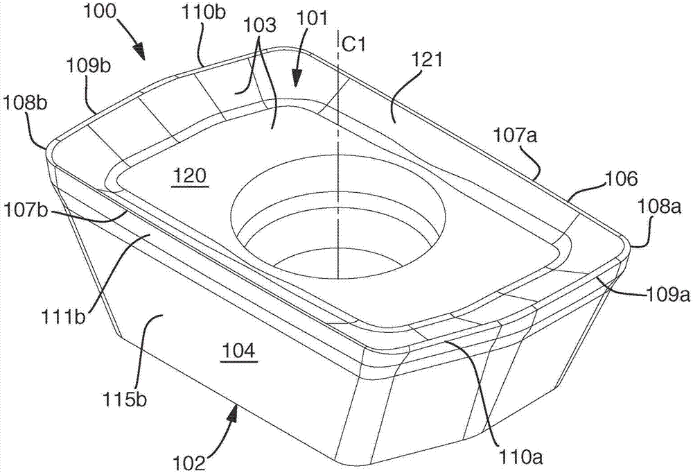
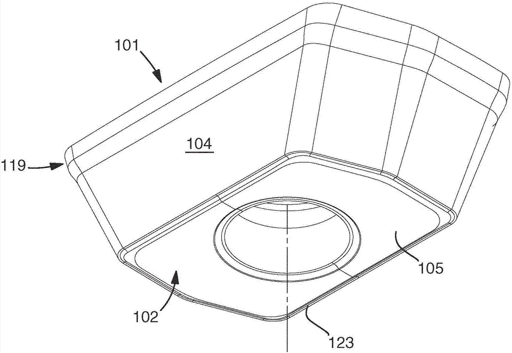
[0037] Figure 1-10 Different views of a milling insert 100 for shoulder milling (ie milling with an entry angle of 90°) according to an embodiment of the invention are shown. The milling insert 100 can be indexed with two index positions and has a positive basic shape. It comprises an upper side 101 and a lower side 102 opposite the upper side 101 . The central axis C1 extends between the upper side 101 and the lower side 102 . A central hole is provided for mounting the milling insert in the tool body. The upper side 101 includes a rake face 103 having a planar central region 120 extending around the central bore. The underside 102 includes a planar counter surface 105 . The flank face 104 extends around the periphery of the milling insert. The cutting edge 106 is formed between the rake face 103 and the flank face 104 . Upper extension plane P U is defined to extend parallel to the bed face 105 at the level of the cutting edge 106 . The cutting edge 106 and the uppe...
PUM
 Abstract
Description
Claims
Application Information
 - R&D
- Intellectual Property
- Life Sciences
- Materials
- Tech Scout
- Unparalleled Data Quality
- Higher Quality Content
- 60% Fewer Hallucinations
Browse by: Latest US Patents, China's latest patents, Technical Efficacy Thesaurus, Application Domain, Technology Topic, Popular Technical Reports.
© 2025 PatSnap. All rights reserved.Legal|Privacy policy|Modern Slavery Act Transparency Statement|Sitemap|About US| Contact US: help@patsnap.com